| Aspect | Internet | Intranet |
|---|---|---|
| Connectivity | Publicly accessible, global connectivity | Private network, limited to a specific organization |
| Accessibility | Open to the public | Restricted access within the organization |
| Security | Higher security concerns due to public access | Generally more secure, as it’s within a controlled environment |
| Purpose | Facilitates global communication and access | Supports internal communication and collaboration |
| Scope | Extensive, covers the entire globe | Limited to the organization’s premises |
| Speed | Speed can vary based on global network conditions | Typically faster due to localized infrastructure |
| Examples | World Wide Web (WWW), public websites | Internal portals, shared databases, communication platforms |
| Administration | Managed by multiple entities and ISPs | Controlled and administered by the organization |
| Cost | Usage may involve costs for bandwidth and hosting | Costs associated with setup and maintenance, usually less expensive |
| Independence | Independent of any single organization | Tied to the specific organization’s needs |
Nuts-and-Bolts Description
Internet is a network, I know, but of what? The Internet is a computer network that interconnects billions of computing devices throughout the world. Increasingly, nontraditional internet things such as laptops, smartphones, tablets, TVs, gaming consoles, thermostats, home appliances, watches, eye glasses are being connected to the Internet. In Internet jargon, all of these devices are called hosts or end systems
End systems: End systems are connected together by a network of communication links and packet switches. There are many types of communication links which are made up of different types of physical media, including coaxial cable, copper wire, optical fiber, and radio spectrum. Packet switches come in many shapes and flavors, but the two most prominent types in today’s Internet are routers and link-layer switches. Different links can transmit data at different rates, with the transmission rate of a link measured in bits/second.
Communication links: When one end system has data to send to another end system, the sending end system segments the data and adds header bytes to each segment. The resulting packages of information, known as packets in the jargon of computer networks, are then sent through the network to the destination end system, where they are reassembled into the original data.
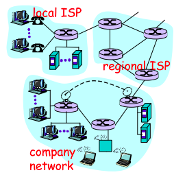
Tell me more about internals of what’s connecting end systems. End systems access the Internet through Internet Service Providers (ISPs), including residential ISPs such as local cable or telephone companies; corporate ISPs; university ISPs; ISPs that provide WiFi access in airports, hotels, coffee shops, and other public places; and cellular data ISPs, providing mobile access to our smartphones and other devices. Each ISP is in itself a network of packet switches and communication links. ISPs provide a variety of types of network access to the end systems, including residential broadband access such as cable modem or DSL, high-speed local area network access, and mobile wireless access. ISPs also provide Internet access to content providers, connecting Web sites and video servers directly to the Internet.
How are these all end systems and ISPs in coordination? The Internet is all about connecting end systems to each other, so the ISPs that provide access to end systems must also be interconnected. These lower-tier ISPs are interconnected through national and international upper-tier ISPs such as Level 3 Communications, AT&T, Sprint, and NTT. An upper-tier ISP consists of high-speed routers interconnected with high-speed fiber-optic links. Each ISP network, whether upper-tier or lower-tier, is managed independently, runs the IP protocol, and conforms to certain naming and address conventions.
Services Description
In addition to traditional applications such as e-mail and Web surfing, Internet applications include mobile smartphone and tablet applications, including Internet messaging, mapping with real-time road-traffic information, music streaming from the cloud, movie and television streaming, online social networks, video conferencing, multi-person games, and location-based recommendation systems.
The applications are said to be distributed applications, since they involve multiple end systems that exchange data with each other.
End systems attached to the Internet provide a socket interface that specifies how a program running on one end system asks the Internet infrastructure to deliver data to a specific destination program running on another end system. This Internet socket interface is a set of rules that the sending program must follow so that the Internet can deliver the data to the destination program.
The Network Edge
End systems are also referred to as hosts because they host that is, run application programs such as a Web browser program, a Web server program, an e-mail client program, or an e-mail server program. Hosts are sometimes further divided into two categories: clients and servers. Informally, clients tend to be desktop and mobile PCs, smartphones, and so on, whereas servers tend to be more powerful machines that store and distribute Web pages, stream video, relay e-mail, and so on. Today, most of the servers from which we receive search results, e-mail, Web pages, and videos reside in large data centers.
Having considered the applications and end systems at the edge of the network, the network that physically connects an end system to the first router (also known as the “edge router”) on a path from the end system to any other distant end system are the access networks.
The access ISP does not have to be a telco or cable company; instead it can be, for example, a university providing Internet access to student, staff and faculty. But connecting end users and content providers into an access ISP is only a small piece of solving the puzzle of connecting the billions of end systems that make up the Internet. To complete this puzzle, the access ISPs themselves must be interconnected which is done by creating a network of networks.
(The Edge Network) (see: conversion techniques, information theory;)
What is even a protocol? All activity in the Internet that involves two or more communicating remote entities is governed by a protocol. For example, hardware-implemented protocols in two physically connected computers control the flow of bits on the wire between the two network interface cards; congestion-control protocols in end systems control the rate at which packets are transmitted between sender and receiver; protocols in routers determine a packet’s path from source to destination.
A protocol defines the format and the order of messages exchanged between two or more communicating entities, as well as the actions taken on the transmission and/or receipt of a message or other event.
The Network Core
Having examined the Internet’s edge, now delve more deeply inside the network core - the mesh of packet switches (see switching:) and links that interconnects the Internet’s end systems. Much of evolution of Internet is driven by economics and national policy rather than by performance considerations. Let’s incrementally build a series of network structures, with each new structure being a better approximation of the complex internet we have today.
Naive approach (mesh ISPs) One naive approach would be to have each access ISP directly connect with every other access ISP, such a mesh design is, of course, much too costly for the access ISPs, as it would require each access ISP to have a separate communication link to each of the hundreds of thousands of other access ISPs all over the world.
Structure 1 (start ISPs) Our first network structure, interconnects all of the access ISPs with a single global transit ISP, which is a network of routers and communication links that not only spans the globe, but also has at least one router near each of hundreds of thousands of access ISPs. It would be very costly for the global ISP to build such an extensive network. To be profitable, it would naturally charge each of the access ISPs for connectivity, with the pricing reflecting the amount of traffic an access ISP exchanges with the global ISP.
Structure 2 Now If some company builds and operates a global transit ISP that is profitable then it is natural for other companies to build their own global transit ISPs and compete with the original global transit ISP which leads to another structure that consists of hundreds of thousands of access ISPs and multiple global transit ISPs. However, the global transit ISPs themselves must interconnect: otherwise access ISPs connected to one of the global transit providers would not be able to communicate with access ISPs connected to other global transit providers. This is a two-tier hierarchy with global transit providers residing at the top tier and access ISPs at the bottom tier. This assumes that global transit ISPs are not only capable of getting close to each and every access ISP, but also find it economically desirable to do so.
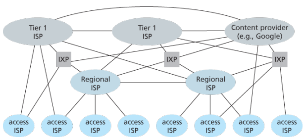
Structure 3 In reality, although some ISPs do have impressive global coverage and do directly connect with many access ISPs, no ISP has presence in each and every city in the world. Instead, in any given region, there may be a regional ISP to which the access ISPs in the region connect. Each regional ISP then connects to tier-1 ISPs. Tier-1 ISPs are similar to our (imaginary) global transit ISP; but tier-1 ISPs, which actually do exist, do not have a presence in every city in the world. There are approximately a dozen tier-1 ISPs, including Level 3 Communications, AT&T, Sprint, and NTT. Each regional ISP then connects to tier-1 ISPs. An access ISP can also connect directly to a tier-1 ISP, in which case it pays the tier-1 ISP. To further complicate matters, in some regions, there may be a larger regional ISP (possibly spanning an entire country) to which the smaller regional ISPs in that region connect; the larger regional ISP then connects to a tier-1 ISP.
Structure 4 The amount that a customer ISP pays a provider ISP reflects the amount of traffic it exchanges with the provider. To reduce these costs, a pair of nearby ISPs at the same level of the hierarchy can peer, that is, they can directly connect their networks together so that all the traffic between them passes over the direct connection rather than through upstream intermediaries. When two ISPs peer, it is typically settlement-free, that is, neither ISP pays the other. As noted earlier, tier-1 ISPs also peer with one another, settlement-free. Along these same lines, a third-party company can create an Internet Exchange Point (IXP), which is a meeting point where multiple ISPs can peer together. An IXP is typically in a stand-alone building with its own switches. There are over 400 IXPs in the Internet today.
Structure 5 We now finally arrive at Network Structure 5, which describes today’s Internet builds on top of Network Structure 4 by adding content-provider networks. Google is currently one of the leading examples of such a content-provider network. The Google data centers are all interconnected via Google’s private TCP/IP network, which spans the entire globe but is nevertheless separate from the public Internet. Importantly, the Google private network only carries traffic to/from Google servers. The Google private network attempts to “bypass” the upper tiers of the Internet by peering (settlement free) with lower-tier ISPs, either by directly connecting with them or by connecting with them at IXPs. However, because many access ISPs can still only be reached by transiting through tier-1 networks, the Google network also connects to tier-1 ISPs, and pays those ISPs for the traffic it exchanges with them. By creating its own network, a content provider not only reduces its payments to upper-tier ISPs, but also has greater control of how its services are ultimately delivered to end users.
Network Standardization (Who is Who?)
The legal status of the world’s telephone companies varies considerably from country to country. At one extreme is the United States, which has over 2000 separate, privately owned telephone companies. At the other extreme are countries in which the national government has a complete monopoly on all communication, including the mail, telegraph, telephone, and often radio and television.
With all these different suppliers of services, there is clearly a need to provide compatibility on a worldwide scale to ensure that people (and computers) in one country can call their counterparts in another one. In 1865, representatives from many European governments met to form the predecessor to today’s ITU. Its job was to standardize international telecommunications, which in those days meant telegraphy. In 1947, ITU became an agency of the United Nations.
International standards are produced by ISO, a voluntary non-treaty organization founded in 1946. Its members are the national standards organizations of the 157 members countries. On issues of telecommunication standards, ISO and ITU-T often cooperate (ISO is a member of ITU-T) o avoid the irony of two official and mutually incompatible international standards.
NIST (National Institute of Standards and Technology) is part of the U.S. Department of Commerce. It used to be called the National Bureau of Standards. It issues standards that are mandatory for purchases made by the U.S. Government, except for those of the Department of Defense, which defines its own standards.
Another major player in the standards world is IEEE (Institute of Electrical and Electronics Engineers), the largest professional organization in the world. In addition to publishing scores of journals and running hundreds of conferences each year, IEEE has a standardization group that develops standards in the area of electrical engineering and computing.
When the ARPANET was set up, DoD created an informal committee to oversee it. In 1983, the committee was renamed the Internet Activities Board (IAB). Each of the approximately ten members of the IAB headed a task force on some issue of importance. The IAB met several times a year to discuss results and to give feedback to the DoD and NSF, which were providing most of the funding at this time. Communication was done by a series of technical reports called RFCs (Request For Comments).
By 1989, the Internet had grown so large that this highly informal style no longer worked. Many vendors by then offered TCP/IP products and did not want to change them just because ten researchers had thought of a better idea. In the summer of 1989, the IAB was reorganized again. The researchers were moved to the IRTF (Internet Research Task Force), which was made subsidiary to IAB, along with the IETF (Internet Engineering Task Force).
For Web standards, the World Wide Web Consortium (W3C) develops protocols and guidelines to facilitate the long-term growth of the Web. It is an industry consortium led by Tim Berners-Lee and set up in 1994 as the Web really begun to take off.
RFC in depth:
A RFC is a publication in a series from the principal technical development and standards-setting bodies for the Internet, most prominently the IETF. An RFC is authored by individuals or groups of engineers and computer scientists in the form of a memorandum describing methods, behaviors, research, or innovations applicable to the working of the Internet and Internet-connected systems. It is submitted either for peer review or to convey new concepts, information, or occasionally, engineering humor.
- The IETF adopts some of the proposal published as RFCs as Internet Standards. However, many RFCs are informational or experimental in nature and are not standards.
- The official source for RFCs on WWW is the RFC Editor.
- The RFC Editor assigns RFC a serial number. Once assigned a number and published, an RFC is never rescinded or modified; if the document requires amendments, the authors publish a revised document. Therefore, some RFCs supersede others; the superseded RFCs are said to be deprecated, obsolete, or obsoleted by the superseding RFC.
The RFC series contains three sub-series for IETF RFCs:
- BCP
- FYI
- STD
There are five streams of RFCs: IETF, IRTF, IAB, independent submission and Editorial.
Each RFC is assigned a designation with regard to status within the Internet standardization process. This status is one of the following:
- Informational,
- Experimental,
- BCP,
- Standards Track,
- Historic
Example:
- IPv4 RFC 791 “Internet Protocol”
- TCP RFC 793 “Transmission Control Protocol”
ICANN
The Internet Corporation for Assigned Names and Numbers (ICANN) is an American multistakeholder group and nonprofit organization responsible for coordinating the maintenance and procedures of several databases related to the namespaces and numerical spaces of the Internet, ensuring network’s stable and secure operation.
ICANN performs the actual technical maintenance work of the Central Internet Address pools and DNS root zone registries pursuant to the Internet Assigned Numbers Authority (IANA) function contract.
Much of its work has concerned the Internet’s global Domain Name System (DNS), including policy development for internationalization of the DNS, introduction of new generic top level domains (TLDs), and the operation of root name servers.
DNS Management: ICANN oversees the global DNS, ensuring the stable and secure operation of the system. This involves managing the allocation of domain names and IP addresses, as well as the coordination of root server systems
Accreditation of Registrars: ICANN accredits domain registrars, ensuring they comply with standards and policies. Registrars act as intermediaries between individuals or organizations and the domain registration process.
IANA Functions Oversight: ICANN oversees the Internet Assigned Numbers Authority (IANA) functions, which includes
- management of global IP address space,
- assignment of protocol parameters,
- and maintenance of the DNS root zone.
ICANN plays a crucial role in promoting and enhancing the security and stability of the DNS. This includes initiatives to combat cyber threats, support the implementation of DNSSEC (Domain Name System Security Extensions), and address emerging challenges.
Example: In 2013, the initial report of ICANN’s Expert Working Group has recommended that the present form of Whois, a utility that allows anyone to know who has registered a domain name on the Internet, should be abandoned.
In a long-running dispute, ICANN has so far declined to allow a Turkish company to purchase the .islam and .halal gTLDs.
The Registry System:
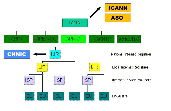
Internet number resources are distributed globally according to a hierarchical registry system that has evolved over the past two decades. The graph shows how Internet number resources are distributed from the central IANA-managed pool to the five Regional Internet Registries and then onto their Members (Local Internet Registries, or LIRs). The IANA has authority over all number spaces used in the internet, including IP address space and AS numbers. IANA allocates public Internet address space to RIRs according to their established needs.
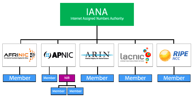
The duty of an RIR include the coordination and representation of the members in its region. Additional RIRs may be established in the future, although their number will remain relatively low. The RIRs work closely together to develop consistent policies and promote best current practice for the Internet.
-
LIRs are established under the authority of an RIR. LIRs are typically operated by Internet Service Providers and serve the customers of those ISPs. Other organizations such as large Enterprises can also operate LIRs.
-
An entity that uses IP address space for its network only and does not provide IP/ASN services to customers is called an End User. Strictly speaking, End Users are not part of the Internet Registry System. They do, however, play an important role with respect to the goals defined above. In order to achieve the conservation goal, for example, End Users should plan their networks to use a minimum amount of address space. They must document their addressing and deployment plans to the LIR and furnish any additional information required by the LIR for making assignment decisions. To achieve the aggregation goal, an End User should choose an appropriate LIR. End Users should be aware that changing ISPs may require replacing addresses in their networks.
-
In addition to these key players in the Internet Registry System, there are often consultants who set up and manage networks for End Users. The consultants may be the persons submitting a request for address space to an LIR on behalf of an End User. We refer to the person making the request for an End User as a requester, whether that person is employed by the organisation, or is simply acting on behalf of the organisation with respect to the address space request.
-
With regard to Internet number resources, IANA’s role is to allocate IP addresses and AS Numbers from the pools of unallocated resources to RIRs according to their needs, and to document assignments made by the IETF. When an RIR requires more addresses for allocation or assignment within its region, IANA makes an additional allocation to the RIR.
Backbones of Internet
Optical backbone:
Marine cables:
Satellites:
Teleports:
A telecommunications port is a satellite ground station with multiple parabolic antennas that functions as a hub connecting a satellite or geocentric orbital network with a terrestrial telecommunications network.
Domain Name System
Internet hosts are identified by IP addresses which is four bytes and has a rigid hierarchical structure. People rather prefer the more mnemonic host-name identifier, while routers prefer IP, in order to reconcile these preferences, need a directory service that translates hostnames to IP addresses.
The DNS is a collective term for a distributed database implemented in a hierarchy of DNS servers and an application-layer protocol that allows hosts to query the distribute database
The DNS servers are often UNIX machines running the Berkeley Internet Name Domain (BIND) software, which runs over UDP and uses port 53.
DNS is commonly employed by other application-layer protocols -including HTTP and SMTP to translate user-supplied hostnames to IP addresses. As an example, when a browser that is, HTTP client running on some user’s host requests the URL , in order for the user’s host to be able to send an HTTP request message to the Web server, the user’s host must first obtain the IP address of .
DNS provides few other important services in addition to translating hostnames to IP addresses:
-
Host alisaing: A host with a complicated hostname can have one or more alias names, for ex: a hostname such as could have, say, two aliases such as and , in this case is said to be canonical hostname. Alias hostnames, when present, are typically more mnemonic than canonical hostnames. DNS can be invoked by an application to obtain the canonical hostname for a supplied alias hostname as well as the IP address of the host.
-
Mail aliasing: The hostname of Yahoo mail server is more complicated and much less mnenomic than simply . DNS can be invoked by a mail application to obtain the canonical hostname for a supplied alias as well as the IP address of the host.
-
Load distribution: DNS is also used to perform load distribution among replicated servers such as replicated Web servers, for replicated Web servers. Busy sites, such as cnn.com , are replicated over multiple servers, with each server running on a different end system and each having a different IP address. For replicated Web servers, a set of IP addresses is thus associated with one canonical hostname. When clients make a DNS query for a name mapped to a set of addresses, the server responds with the entire set of IP addresses, but rotates the ordering of the addresses with each reply.
How DNS works for hostname-to-IP-address translation service?
When some applicaiton running in a user’s host needs to translate a hostname to an IP address, the application invokes the client side of DNS, specifying the hostname that needs to be translated. On many UNIX-based machines, is the function call that an application calls in order to perform the translation.
DNS in the user’s host then takes over, sending a query message into the network. All DNS query and replies are sent within UDP datagrams to port 53. After a delay ranging from milliseconds to seconds, DNS in the user’s host receives a DNS message that provides the desired mapping. This mapping is then passed to the invoking application.
The hierarchy of DNS servers?
A simple design for DNS would have one DNS server that contains all the mappings. Although the simplicity of this design is attractive, it is inappropriate for today’s Internet with its vast number of hosts.
A centralized database in a single DNS server simply does not scale, consequently DNS is distribued by design.
In order to deal with the issue of scale, the DNS uses a large number of servers, organized in a hierarchial fashion and distributed around the world. No single DNS server has all of the mappings for all of the hosts in the Internet. Instead the mappings are distributed across the DNS servers.
To a first approximation, there are three classes of DNS servers -root DNS servers, top-level doman (TLD) DNS, and authoritative DNS organized in a hierarchy. Suppose a DNS client wants to determine the IP address for the hostname amazon.com. The client first contacts one of the root servers, which return IP addresses for TLD servers for the top-level domain com. The client then contacts one of these TLD servers, which returns the IP address of an authorative server for amazon.com. Finally, the client contacts one of the authorative servers for amazon.com which returns the IP address for the hostname.
-
Root DNS servesr. There are over 400 root name serves scattered all over the world. These root name servers are managed by 13 different organizations. Root name servers provide the IP addresses of the TLD servers.
-
For each top-level domains, such as com, org, net, edu, gov, and all of the country top-level domain there is TLD server (or server cluster). The company Verisign Global Registry Services maintains the TLD servers for the com top-level domain. TLD servers provide IP for authoritative DNS servers.
-
Authoritative DNS servers. Every organization with publicly accessible hosts such as Web servers and mail servers on the Internet must provide publicly accessible DNS records that map the names of those hosts to IP addresses. An organization’s authoritative DNS server houses these DNS records. An organization can choose to implement its own authoritative DNS server to hold these records; alternatively, the organization can pay to have these records stored in an authoritative DNS server of some service provider.
There is an another important type of DNS server called the local DNS server, does not strictly belong to the hierarchy of servers but is nevertheless central to the DNS architecture.
Each ISP - such as a residential ISP or an institutional ISP - has a local DNS server (also called a default name server). When a host connects to an ISP, the ISP provides the host with the IP addresses of one or more of its local DNS servers typically through DHCP.
A host’s local DNS server is typically close to the host, for an institutional ISP, the local DNS server may be on the same LAN as the host; for a residential ISP, it is typically separated from the host by no more than a few routers.
Example: Suppose the host cse.nyu.edu desires the IP address of gaia.cs.umass.edu. NYU’s local DNS server is dns.nyu.edu and that an authoritative DNS server for gaia.cs.umass.edu is called dns.umass.edu.
1. The host cse.nyu.edu first sends a DNS query message to its local DNS server, dns.nyu.edu containing the hostname to be translated namely gaia.cs.umass.edu.
2. The local DNS server forwards the query message to root DNS server which takes note of the edu suffix and returns to the local DNS server a list of IP addresses for TLD servers responsible for edu.
3. The local DNS server then re-sends the query message to one of these TLD servers which takes note of the umass.edu suffix and responds with the IP address of the authoritative DNS server for the University of Massachusetts, namely, dns.umass.edu
4. Finally query is send directly to dns.umass.edu which responds with the IP address of gaia.cs.umass.edu
Eight DNS messages were sent, assuming that the TLD server knows the authoritative DNS server for the hostname, which is not always true, instead the TLD server may know only of an intermediate DNS server, which in turn knows the authoritative DNS server for the hostname.
(yesma bhannu parda intermediate authorative dns server hunxa rey, yei case ma ni dns.cs.umass.edu bhanni chai harek deparment ma bhako servers ko authorative huna payo, testai garera, yesko authorative arko kunai intermediate hunxa)
![[Screenshot from 2023-09-11 23-37-36.png]]
The query from the requesting host to the local DNS server is recursive, and the remaining queries are iterative.
DNS caching -DNS extensively exploits DNS caching in order to improve the delay performance and to reduce the number of DNS messages -In a query chain, when a DNS server receives a DNS reply, it can cache the mapping in its local memory -Because hosts and mappings between hostnames and IP addresses are by no means permanent, DNS servers discard cached information after a period of time often set to two days -A local DNS server can also cache the IP addresses of TLD servers, thereby allowing the local DNS server to bypass the root DNS servers in a query chain -As a result, root servers are bypassed for all but a very small fraction of DNS queries
DNS Records and Messages -The DNS servers that together implement the DNS distributed database store resource records (RRs), so each DNS reply message carries one or more resource records -A resource record is a four-tupel that contains the following fields:
(Name, Value, Type, TTL)

-TTL is the time to live of the resource record; it determines when a resource should be removed from a cache
-The meaning of Name and Value depend on Type:

1. If Type=A, then Name is a hostname and Value is the IP address for the hostname
2. If Type=Ns, then Name is a domain and Value is the hostname of an authorative DNS server that knows how to obtain the IP addresses for hosts in the domain
3. If Type=CNAME, then Value is a canoncial hostname for the alias hostname Name
4. If Type=MX, then Value is the canonical name of a mail server that has an alias hostname Name

-If a DNS server is authorative for a particular hostname, ten the DNS server will contain a Type A record for the hostname, even if it is not, may contain a Type A record in its cache
-If not authorative, then will contain a Type NS record for the domain that includes the hostname; along with it will also contain a Type A record that provides the IP address of the DNS server in the Value filed of the NS record (bhaneko agadi yo hostname ko lag authorative hosst yo ho ra tyo authorative host ko IP pani ta chaiyo ni sathi haru)

DNS Messages:
-There are only two kinds of DNS messages, both query and reply have the same format
-The first 12 bytes is the header section, which has a number of fields, first is a 16 bit number that identifies the query, which is copied into the reply message to a query, allowing the client to match received replies with sent queries
-
.....
-To send query directly from the host to some DNS server can be done with nslookup program
Inserting records into the DNS Database: -To register a domainname networkutopia.com at a registar which is a commerical entity that verifies the uniquess of the domain name, wchic enters the domain name into the DNS database, and collects a small fee from you for its services -There are many regisrars competing for customers, and the ICANN accredits the various registrars -When you register the domain name networkutopia.com with some registrar, you need to provide the registrar with the names and IP addresses of you rprimarly and secondary authorative DNS servers -Suppose the names and IP addresses are dns1.networkutopia.com, dns2.networkutopia.com, 212.2.212.1 and 212.212.212.2, for each of thse authorative DNS servers, the registrar would then make sure that a Type NS and Type A record are entered into the TLD com servers -Also need to make sure that the Type A resource record for your Web server and Type MX for your mail server are entered into your authorative DNS -Until recently, the conents of each DNS server were configured statically, for ex, from a configuration file created by a system manager -More recently, an UPDATE option has been added to the DNS protocl to allow data to be dynamically added or dleted from the database via DNS messages
N - tier Client Server Architecture
The client-server model is a distributed application structure that partitions tasks or workloads between the providers of a resource or service, called servers, and service requesters, called clients. Often clients and servers communicate over a computer network on separate hardware, but both client and server may reside in the same system as well.
N-tier application architecture provides a model by which developers can create flexible and reusable applications. By segregating an application into tiers, developers acquire the option of modifying or adding a specific tier, instead of reworking the entire application.
A server host runs one or more server programs, which share their resources with clients. A client usually does not share any of its resources, but it requests content or service from a server. Clients, therefore, initiate communication sessions with servers, which await incoming requests. Examples of computer applications that use the client-server model are email, network printing, and the WWW.
Traditional systems: Users interact with these systems through terminals (keyboards and screens) that have no processing capability of their own; they simply send their input to the mainframe and display the results of processing. This model is highly centralized, with the mainframe at the core handling all computations, storage, and management tasks.
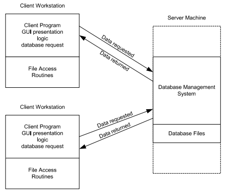
2-tier architecture:
Operational layers:
- Client layer (presentation tier): user interface layer where the application is accessed and interacted with by the user. It resides on the client side.
- Server layer (data tier): includes the database management system, where the data is stored, retrieved, and updated. It processes requests from the client layer and sends back the results.
Key points:
- Direct communication
- Simplicity
- Scalability issues: adding more clients or increasing database size can significantly impact performance
- Maintenance: changes in the database structure can require updates to the client-side application
3-tier architecture:
Operational layers:
- Presentation tier client: user interface where the application is accessed by the user, solely focuses on presenting the data to the user. The presentation layer displays information related to services such as browsing merchandise, purchasing and shopping cart contents. It communicates with other tiers by which it puts out the results to browser/client tier and all other tier in network.
- Application tier: acts as an intermediary between the presentation tier and the data tier, processes business logic, computations and makes logical decisions. It controls an application’s functionality by performing detailed processing.
- Data tier: consists of DBMS
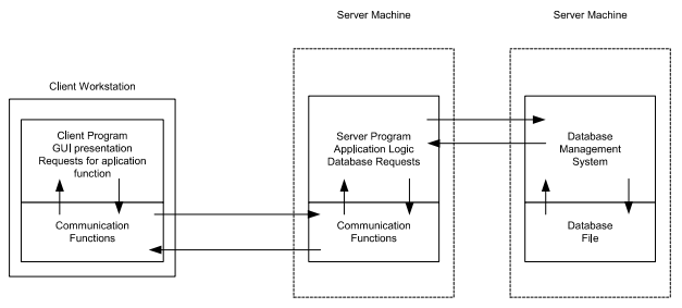
Key points:
- Enhance scalability
- Improved security
- Flexibility
- Complexity
The Web and HTTP
The Internet was essentially unknown outside of the academic and research communities, the Web was the first Internet application that caught the general public’s eye.
Most appealing of the Web is operating on demand, users receive what they want, when they want it, which is unlike traditional broadcast radio and television, which force users to tune in when the content provider makes the content available.
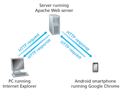
The HTTP is at the heart of the Web. HTTP is implemented in two programs: a client program and a server program, executing on different end systems, talk to each other by exchanging HTTP messages.
A web page consists of objects, an object is simply a file such as an HTML file, a JPEG image, or a video clip -that is addressable by a single URL. Most web pages consist of a base HTML file and several referenced objects. For example, if a web page consists HTML text and five JPEG, then the web page has six objects, the base HTML plus other fives images.
Each URL has two components: the hostname of the server that houses the object and the object’s path name. For example: has as a hostname and for a path name.
A segway:
URIs and URLs have a shared history. Tim Berners-Lee’s proposals for hypertext implicitly introduced the idea of URL as a short string representing resource that is the target of a hyperlink. Over the next three and a half years, as the WWW core technologies of HTML, HTTP, and Web browsers developed, a need to distinguish a string that provided an address for a resource from a string that merely named a resource emerged. Although not yet formally defined, the term Uniform Resource Locator came to represent the former, and the more contentious Uniform Resource Name came to represent the latter.
Every HTTP URL conforms to the syntax of a generic URI. The URI generic syntax consists of five components organized hierarchically in order of decreasing significance from left to right:
URI = scheme ":" ["//" authority] path ["?" query] ["#" fragment]
The authority component consists of subcomponents:
authority = [userinfo "@"] host [":" port]

Back: Web browsers implement the client side of HTTP. Web servers implement the server side of HTTP, house Web objects addressable by a URL. Popular Web servers include Apache and Microsoft Information Sever.
HTTP defines how Web clients request Web pages (or objects?) from Web servers and how servers transfer Web pages to clients. When a user requests a Web page the browser sends HTTP request messages for the objects in the page to the server, the server receives the requests and responds with HTTP response messages that contain the objects.
HTTP uses TCP as its underlying transport protocol rather than running on top of UDP. The HTTP client initiates a TCP connection with the server. Once the connection is established, the browser and the server processes access TCP through their socket interfaces.
Once the client sends a message into its socket interface, the message is out of the client’s hands and is in the hands of TCP which implies that the message eventually arrives intact at the server. The server sends requested files to clients without storing any state information about the client, it completely forgets what it did earlier, HTTP is said to be a stateless protocol.
Non persistent vs persistent:
In many Internet applications, the client and server communicate for an extended period of time, with the client making a series of requests and the server responding to each of the requests. Depending on the application and on how the application is being used, the series of requests may be made back-to-back, periodically at regular intervals, or intermittently, the application developer needs to make an important decision -should each request/response pair be send over a separate (non-persistent) or same (persistent) TCP connection? Although HTTP uses persistent connections in its default mode, HTTP clients and servers can be configured to use non-persistent connections instead.
Non-persistent connections:
- Steps of transferring a web page that consists of a base HTML file and 10 JPEG images and all 11 of these objects reside on the same server
http://www.someschool.edu/someDepartment/home.index. - HTTP client process initiates a TCP connection to the server
someschool.eduon port number 80, which is the default port number for HTTP, associated with the TCP connection, there will be a socket at the client and a socket at the server. - Client sends a HTTP request that includes the path name /someDeparment/home.index
- Server process receives the request message via its socket, retrieves the object from its storage, encapsulates the object in an HTTP response message, and sends to the client via its socket
- HTTP server process tells TCP to close the TCP connection but TCP doesnot actually terminate the connection until it knows for sure that the client has received the response message intact
- HTTP client receives the response message, the TCP connection terminates, the message indicates that the encapsulated object is an HTML file, the client extracts the file from the response message, examines the HTML file, and finds references to the 10 JPEG objects
- The first four steps are then repeated for each of the referenced JPEG objects.
Note that TCP connection transports exactly one request message and one response message, hence 11 TCP connections are generated. Users can configure modern browsers to control the degree of parallelism, in their default modes, most browsers open 5 to 10 parallel TCP connections and each of these connections handles one request-response transaction.
To initiate a TCP connection involves three way handshake, the client sends a small TCP segment to the sever, the server acknowledges and responds with a small TCP segment, and finally, the client acknowledges back to the server with the HTTP request message. Thus, roughly, the total response time is two round-trip times plus the transmission time at the server of the HTML file.
Persistent connections:
- For each of non-persistent connections, TCP buffers must be allocated and TCP variables must be kept in both the client and server, can be a significant burden on a Web server, which may be serving requests from hundreds of different clients
- Each object suffers a delivery delay of two RTTs
- With HTTP 1.1 persistent connections, the server leaves the TCP connection open after sending a response, subsequent requests and responses between the same client and server can be sent over the same connection
- Multiple web pages residing on the same server can be sent from the server to the same client over a single persistent TCP connection, can be made back to back without waiting for replies to pending requests (pipelining)
- Typically HTTP server closes a connection when it isnt used for a certain time (a configurable timeout interval)
- HTTP/2 allows multiple requests and replies to be interleaved in the same connection, and a mechanism for priotizing HTTP message requests and replies within this connection
HTTP Message format:
There are two types of HTTP messages, request messages and response messages
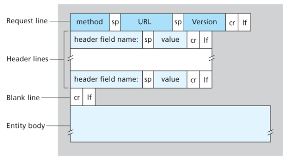
General format of HTTP request message:
Properties
- Message is written in ordinary ASCII text.
- Message consists of five lines, each followed by a carriage return and a line feed, the last line is followed by an additional carriage return and line feed
- Although this particular has five lines, a request message can have many more lines or as few as one line
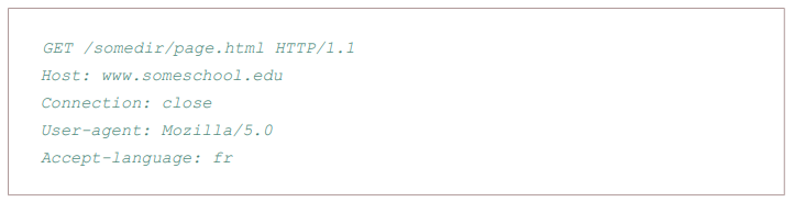
- The first line of an HTTP request is the request line; subsequents are header lines
- The request line has three fields: the method field, the URL field, and the HTTP version field
- The method field can take on several different values, including GET, POST, HEAD, PUT, and DELETE
- Great majority of HTTP request message use the GET method, which is used when the browser requests an object, with the requested object identified in the URL field
- The header line Host specifies the host on which the object resides, which seems unnecessary, as there is already a TCP connection in place to the host but the information provided by the host header is required by Web proxy caches.
- By providing Connection header line, the browser is telling the server that it does not want to bother with persistent connections; it wants the server to close the connection after sending the requested object.
- The User-agent: header specifies the user agent, that is, browser type that is making the request to the server which is useful because the server can actually send different versions of same object to different types of user agents
- The Accept-language indicates the version of the object that the user prefers
- The entity body is empty with the GET method, but is used with the POST method
- An HTTP client often uses the POST method when the users fills out a form -for example, when a user provides search words to a search engine, with a POST message, the user is still requesting a Web page from the server, but the specific contents of the Web page depends on what the user entered into the form fields
- A request generated with a form does not necessarily use the POST method, instead HTML forms often use the GET method and include the inputted data in the form fields in the requested URL, if a form uses the GET method, has a field with input ‘monkey’, then the URL will have structure …/search?monkeys
- HEAD method is similar to GET method, when a server requests with the HEAD method, it responds with an HTTP message but leaves out the requested object, often used for debugging
- The PUT method is often used in conjuction with Web publishing tools, allows a user to upload an object to a specific directory on a Web server, used by applications that need to upload objects to Web servers
- The DELETE method allows a user, or an application to delete an object on a Web server
Types:
- GET: Requests a representation of the specified resource. GET requests should only retrieve data and have no effect.
- POST: Used to submit an entity to the specified resource, often causing change in state or side effects on the server.
- PUT: Replaces a current representations of the target resource with the request payload.
- DELETE: Removes the specified resource.
Typical HTTP response message:
Properties:
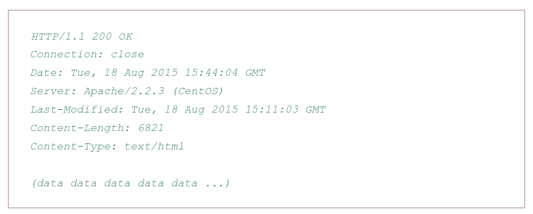
- Has three sections: an initial status line, six header lines, and then the entity body, which is the meat of the message which contains the requested object iself
- The status line has three fields: the protocol version field, a status code, and a corresponding status message, and a corresponding status messagse
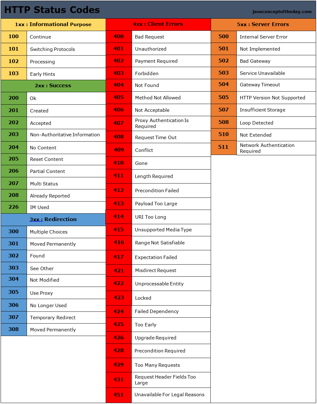
- The status code and associated phrase indicate result of the request, some common status codes and associated phrases:
- 200 OK: Request succeeded and the information is returned in the response
- 301 Moved Permanently: Requested object has been permanently moved; the new URL is specified in Location: header of the response message, client software will automatically retrieve the new URL
- 400 Bad Request: Generic error code indicating that the request could be understood by the server
- 404 Not Found: Requested document does not exist on this server
- 505 HTTP Version Not Supported
- The server uses the Connection: close header line to tell the client that it is going to close the TCP connection after sending the message
- The Date: header line indicates the time and date when the HTTP response was created and sent by the server, which is not when the object was created or last modified
- The Server indicates that the message was generated by an Apache Web server; it is analgous to User-agent header in the HTTP request message
- The Last-Modified is critical for object caching, both in the local client and in network cache servers also known as proxy servers
- The Content-Length: header indicates the number of bytes in the object being sent
- The Content-Type: header line indicates that the object in the entity body is HTML text which is officially indicated by the Content-Type: header and not by the file extension
Real and web browser packets: First telnet into your favourite web server, then type in a one-line request message for some object that is housed on the server
telnet pcampus.edu.np 80
GET /index.html HTTP/2.0
Host: pcampus.edu.np
After carriage return twice, opens a TCP connection to port 80 of the host gais.cs.umass.edu and then sends the HTTP request message
- The HTTP specification defines many, many more header lines that can be inserted by browsers, Web servers, and network cache servers
- A web browser will generate header lines as a function of the browser type and version, the user configuration of the browser, and whether the browser currently has a cached, but possibly out-of-date version of the object, web servers behave similarly
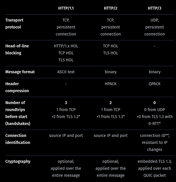
HTTP/1.1
This version came up in early 1997, few months after its predecessor. The main changes were:
- Persistent TCP connections (keep-alive), saving machine and network resources. In the previous version, a new TCP connection was opened for each request and closed after the response
- ‘Host’ header, allowing more than one server under the same IP.
- Header conventions for encoding, cache, language and MIME type.
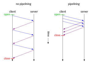
In HTTP/1.1 two requests cannot ride together the same TCP connection - it is necessary that the first one ends for the subsequent to being. This is called head-of-line blocking. In the diagram below, request 2 cannot be sent until response 1 arrives, considering that only one TCP connection is used.
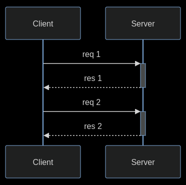
HTTP pipelining is a feature of HTTP/1.1 which allows multiple HTTP requests to be sent over a single TCP connection without waiting for the corresponding responses. The technique was superseded by multiplexing via HTTP/2.
HTTP/2
In 2015, after many years of observation and studies on the performance of the Internet, the HTTP/2 was proposed and created, based on Google’s SPDY.
The working group charter mentions several goals and issues of concern:
- Create a negotiation mechanism that allows clients and servers to elect to use HTTP/1.1, 2.0, or potentially other non-HTTP protocols
- Maintain high-level compatibility with HTTP/1.1
- Decrease latency to improve page load speed in web browsers by considering:
- Data compression of HTTP headers (HPACK compression)
- Prioritization of requests
- Message format: binary?
- Multiplexing multiple requests over a single TCP connection (fixing the HTTP-transaction-level head-of-line blocking problem in HTTP 1.x even when HTTP pipelining is used). HOL blocking in computer networks is a performance limiting phenomenon that occurs when a line of packets is held up in a queue by a first packet.
- Server push: The server can send additional information needed for a request before it is requested?
How HOL is solved?
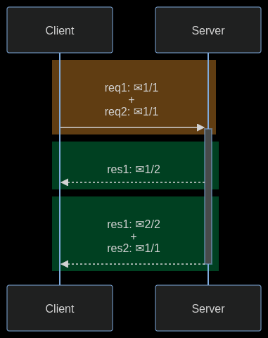
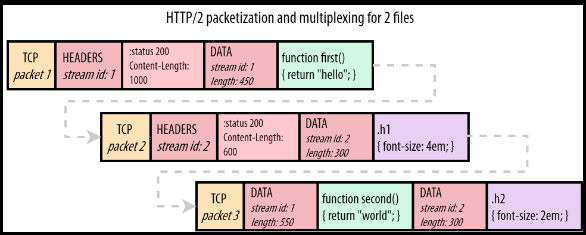
HTTP/2 streams are divided into frames, each one containing: the frame type, the stream that it belongs to, and the length in bytes. In the diagram below, a colored rectangle is a TCP packet and ✉ is a HTTP/2 frame inside it. The first and the third TCP packets carry frames of different streams.
The image below shows how frames go inside a TCP packet. Stream 1 carries a HTTP response for a Javascript file and stream 2 carries a HTTP response for a CSS file.
HTTP/3
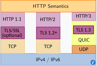
HTTP/3 is a third major version of HTTP used to exchange information on the WWW, complementing widely-deployed HTTP/1.1 and HTTP/2. Unlike previous versions which relied on well-established TCP, HTTP/3 uses QUIC, a multiplexed transport protocol built on UDP.
HTTP/3 uses similar semantics compared to earlier revisions of the protocol, including the same request methods, status codes, and message fields, but encodes and maintains session state differently. However, partially due to the protocol’s adoption of QUIC, HTTP/3 has lower latency and loads more quickly in real-world usage when compared with previous versions: in some cases over 3× faster than with HTTP/1.1
It proposes:
- fewer packets roundtrips to establish connection and TLS authentication
- more resilient connections regarding packet losses
- to solve the head-of-line blocking that exists in TCP and TLS
HTTP/2 solves the HTTP head-of-line blocking, but, this problem also happens with TCP and TLS. TCP understands that the data it needs to send is a contiguous sequence of packets, and if any packet is lost, it must be resent, in order to preserve information integrity. With TCP, subsequent packets cannot be sent until the lost packet is successfully resent to the destination.
To solve TCP’s head-of-line blocking, QUIC decided to use UDP for its transport protocol, because UDP does not care for guarantees of arrival. The responsibility of data integrity, that in TCP is part of the transport layer, is moved in QUIC to the application layer, and the frames of a message can arrive out of order, without blocking unrelated streams.
QUIC allows for a quicker connection establishment compared to traditional TCP handshakes.
Differences:
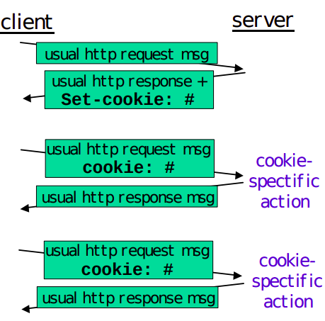
User-server interaction/ cookies:
As HTTP server is stateless, simplifies server design and has permitted engineers to develop high-performance. Web servers that can handle thousands of simultaneous TCP connections. Often desirable for a site to identify users, for these purposes, HTTP uses cookies, which allow sites to keep track of users.
Cooking technology has four components:
- a cookie header line in the HTTP response message
- a cookie header line in the HTTP request message
- a cookie file kept on the user’s end system and managed by the user’s browser
- a back-end database at the Web site
How cookie works?
- When the request comes into the Amazon web server for the first time, the server creates a unique ID and creates an entry in its backend database that is indexed by the ID
- The server then responds back with HTTP response including a Set-cookie header which includes the ID
- When browser receives the HTTP response message, it sees the Set-cookie header, then the browser appends a line to the special cookie file which includes the hostname of the server and the ID in the Set-cookie header
- As the browser continues to request a Web page for the site, puts a cookie header line that includes the ID in the HTTP request
- If the user has registered providing full name, email, then Web server can include this information in database, thereby associating personal information with identification number
Web caching
(more about proxy servers later)
A HTTP proxy server is a network entity that satisfies HTTP requests on the behalf of an origin Web server, which has its own disk storage and keeps copies of recently requested objects in this storage.
A web browser can be configured so that all of the user’s HTTP requests are first directed to the Web cache.
- The browser establishes a TCP connection to the Web cache and sends an HTTP request for the object to the Web cache.
- The Web cache checks to see if it has a copy of the object stored locally, if it does, returns the object within an HTTP response message to the client browser
- If does not, the Web cache opens a TCP connection to the server, then sends an HTTP request for the object into the cache-to-server TCP connection.
Typically is purchase and installed by an ISP
Can substantially reduce the response time for a client request, particularly if the bottleneck bandwidth between the client and the origin server is much less than the bottleneck bandwidth between the client and the cache
Can substantially reduce traffic on an institution’s access link to the Internet
The Content Distribution Networks install many geographically distributed caches throughout the internet, thereby localizing much of the traffic
The Conditional GET:
- Caching can reduce user-perceived response times, introduces a new problem - the copy of an object residing may be stale, may have been modified since the copy was cached at the client.
- HTTP has a mechanism that allows a cache to verify that its objects are up to date called the conditional GET
- So the cache now also stores the last-modified date along with the object, then if another browser requests the same object via the cache, and the object is still in the cache, it performs an up-to-date check by issuing a conditional GET, specifically it sends:
GET /fruit/kiwi.gif HTTP/1.1
Host: www.exotiquecuisine.com
If-modified-since: Wed, 9 Sep 2015 09:23:24
The conditional GET is telling the server to send the object only if the object has been modified since the specified date, if has not been modified then the Web server sends a response message to the cache with empty entity body.
(more details)
The most common use case for conditional requests is updating a cache. With an empty cache, or without a cache, the requested resource is sent back with a status of 200 OK.
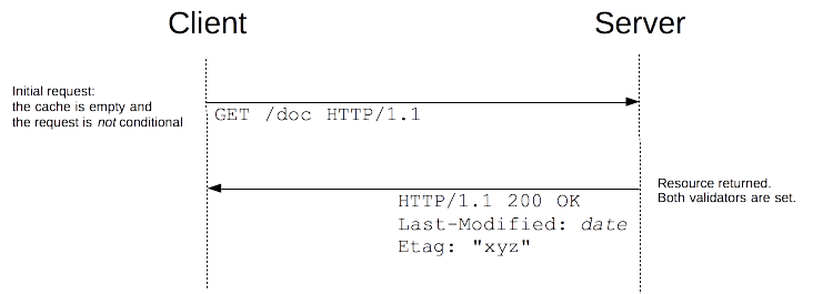
Together with the resource, the validators are sent in the headers. In this example, both Last-Modified and ETag are sent, but it could equally have been only one of them. These validators are cached with the resource (like all headers) and will be used to craft conditional requests, once the cache becomes stale.
As long as the cache is not stale, no requests are issued at all. But once it has become stale, this is mostly controlled by the Cache-Control header, the client does not use the cached value directly but issues a conditional request. The value of the validator is used as a parameter of the If-Modified-Since and If-None-Match headers.
If the resource has not changed, the server sends back a 304 Not Modified response. This makes the cache fresh again, and the client uses the cached resource. Although there is a response/request round-trip that consumes some resources, this is more efficient than to transmit the whole resource over the wire again.
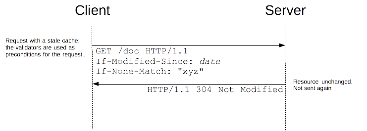 if the resource has changed, the server just sends back a 200 OK response, with the new version of the resource (as through the request wasn’t conditional). The client uses this new resource (and caches it).
HTML
HTML is the standard markup language for documents designed to be displayed in a web browser. It defines the content and structure of web content. It is often assisted by technologies such as CSS and scripting languages such as JavaScript. Web browsers receive HTML documents from a web server or from local storage and render the documents into multimedia web pages. HTML describes the structure of a web page semantically and originally included cues for its appearance.
HTML documents can be delivered by the same means as any other computer file. However, they are often delivered by HTTP from a webserver or by email. Dynamic HTML (DHTML) is a term which was used by some browser vendors to describe the combination of HTML, style sheets, and client-side scripts that enabled the creation of interactive and animated documents.
DHTML allows scripting languages to change variables in a web page’s definition language, which in turn affect the look and function of otherwise static HTML page content after the page has been fully loaded and during the viewing process.
DHTML is the predecessor of Ajax and DHMTL pages are still request/reload-based. Under the DHTML model, there may not be any interaction between the client and server after the page is loaded; all processing happens on the client side. By contrast, Ajax extends features of DHTML to allow the page to initiate network requests (or subrequests) to server even after page load to perform additional actions. For example, if there are multiple tabs on a page, the pure DHTML approach would load the contents of all tabs and then dynamically display only the one that is active, while AJAX could load each tab only when it is really needed.
DHTML is not a technology in and of itself; rather, it is the product of three related and complementary technologies.
Typically a web page using DHTML is set up in the following way:
<!DOCTYPE html>
<html lang="en">

<head>
    <meta charset="utf-8">
    <title>DHTML example</title>
</head>

<body bgcolor="red">
    <script>
        function init() {
            let myObj = document.getElementById("navigation");
            // ... manipulate myObj
        }
        window.onload = init;
    </script>
    <!--
    Often the code is stored in an external file; this is done
    by linking the file that contains the JavaScript.
    This is helpful when several pages use the same script:
    -->
    <script src="my-javascript.js"></script>
</body>

</html>
DOM:
The DOM API is the foundation of DHTML, providing a structure interface that allows access and manipulation of virtually anything in the document. The HTML elements in the document are available as a hierarchical tree of individual objects, making it possible to examine and modify an element and its attributes by reading and setting properties and by calling methods. The text between elements is also available through DOM properties and methods.
In HTML DOM, every element is a node: a document is a document node, all HTML elements are element nodes, all HTML attributes are attribute nodes, text inserted into HTML elements are text nodes, comments are comment nodes.
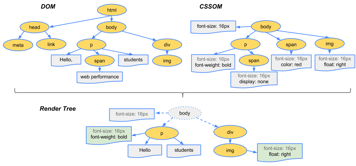
The CSSOM and DOM trees are merged into a render tree, which computes the layout of each visible element and serves as an input to the paint process that renders the pixels to the screen. Optimizing each of these steps is crucial to achieving optimal rendering performance.
To construct the render tree, the browser roughly does the following:
-
Starting at the root of the DOM tree, traverse each visible node
- Some nodes are not visible (for example, script tags, meta tags, and so on), and are omitted since they are not reflected in the rendered output
- Some nodes are hidden via CSS and are also omitted from the render tree; for example, the span node, is missing from the render tree because we have an explicit rule that sets the ‘display:none’ property on it.
-
For each visible node, find the appropriate matching CSSOM rules and apply them
-
Emit visible nodes with content and their computed styles.
At a glance:
Step 1: The browser parses the HTML file first, and that leads to the browser recognizing any link element references to external CSS stylesheets and any script element references to scripts
Step 2: As the browser parses the HTML, it sends request back to the server for any CSS files it has found from link elements, and any JS files it has found from script elements, and from those, then parses the CSS and JS.
Step 3: The browser generates an in-memory DOM tree from the parsed HTML, generates an in-memory CSSOM structure from the parsed CSS, and compiles and executes the parsed JS.
Step 4: As the browser builds the DOM tree and applies the styles from the CSSOM tree (render tree) and executes the JavaScript, a visual representation of the page is painted to the screen, and the user sees the page content and can begin to interact with it.
Let’s talk about Ajax, moving on from DHTML:
AJAX
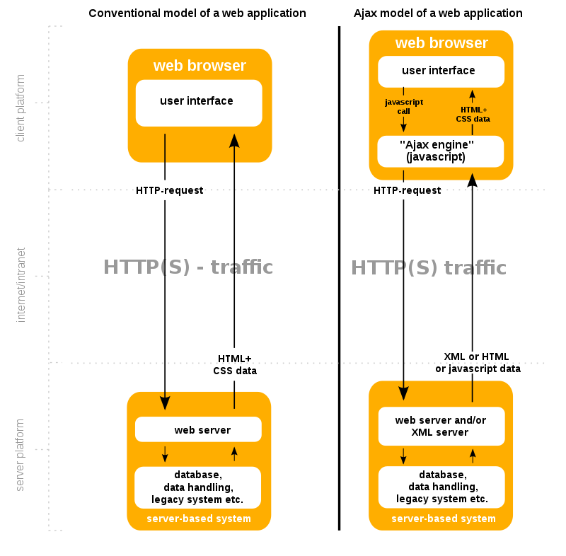
Remember websites in the 90’s?. When you clicked anything, a new page would have to load to show the effect of your click even if it was nothing. That is the internet before AJAX. Now take a look at the very Web with buttons. That’s AJAX for you.
When the browsers send requests to servers for HTML files, those HTML files often contain link elements referencing external CSS stylesheets and script elements referencing external JS scripts.
The term Ajax has come to represent a broad group of Web technologies that can be used to implement a Web application that communicates with a server in the background, without interfering with the current state of the page.
- HTML (or XHMTL) and CSS for presentation
- The DOM for dynamic display of and interaction with data
- JSON or XML for the interchange of data, and XSLT for XML manipulation
- The XMLHttpRequest object for asynchronous communication
- Javascript to bring these technologies together.
Note: The XHR is a JS class containing methods to asynchronously transmit HTTP requests from a web browser to a web server. Fetch is a native JS API. Fetch makes it easier to make web requests and handle responses than the older XHR.
Ajax offers several benefits that can significantly enhance web application performance and user experience. By reducing traffic and improving speed, Ajax plays a crucial role in modern web development. One key advantage of Ajax is its capacity to render web applications without requiring data retrieval, resulting in reduced server traffic. This optimization minimizes response times on both the server and client sides, eliminating the need for users to endure loading screens.
Example of how AJAX works:
-
User Action. The user performs an action (like pressing an up arrow). This button is equipped with an event listener that detects the click.
-
Javascript Call: The event listener triggers a JS function that uses AJAX to send an asynchronous request to the sever. This is typically done using XMLHttpRequest object or the Fetch API.
-
Server Processing: The server receives the request to like the post with ID 12345. It processes this request, which might involve updating the database to record the new like, incrementing the like count for the post, and performing and other necessary logic.
-
Server Response: After processing the request, the server sends a response back to the client. This response might include a status message indicating the request was successful, the new total number of likes for the post, or an error message if something went wrong.
-
Client-side Processing: Once the response is received, the JavaScript code then processes this information. If the action was successful, the code updates the like button to reflect that the user has liked the post. This might involve changing the color of the like button to orange and updating the displayed like count next to the button.
In the absence of AJAX, interacting with a web page, such as liking a post, would require the entire page to reload every time the user performs an action. The user clicks the like button, the page sends a request to the server, then the entire page refreshes to display the updated content, leading to a noticeable interruption in the user experience.
Since we not building the entire page with every click, you can keep information about the site in the browser. This can be used throughout your entire visit and future visits. ReactJs is one of a javascript library for building and maintaining single page applications.
XML
Limitations of HTML:
- HTML is a fixed specification with a finite set of elements. It is not extendable, and as a result of this limitation, Web developers and software vendors have stretched the usefulness of HTML almost to a breaking point.
- Browser vendors such as Microsoft have added proprietary features and additional elements to their browsers based on demands for more functionality, but in so doing, they have compromised one of the most important benefits that HTML has to offer - portability.
- The limitations of HTML made it very clear that a new and better language was necessary for formulating Web documents. In addition, may companies were adding transactional functionality to their Web sites, such as allowing visitors to purchase items and services online.
- This marked a radical departure from the first generation of websites, which mainly provided static information that was easily stored as text. These new websites relied heavily on data gathered from different sources, such as databases, news feeds, and other Web sites
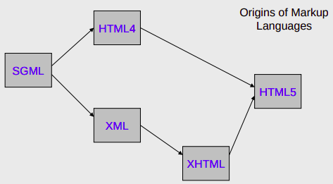
- The resulting language was the XML. XML is an extensive language because, unlike HTML, it allows users to define their own tags.
XML:
XML is a markup language and file format for storing, transmitting, and reconstructing arbitrary data. It defines a set of rules for encoding documents in a format that is both human-readable and machine-readable. The main purpose of XML is serialization, i.e storing, transmitting, and reconstructing arbitrary data. For two disparate systems to exchange information, they need to agree upon a file format. XML standardizes this process.
XML itself is not a language - it is a meta language. A meta language is a set of rules used for building markup languages. Structured languages can be developed that describe certain types of data rather than just the presentation of the data. Such structured languages include elements that describe documents containing information about an account, an item, a service, or a transaction. XHTML is an application of XML that is used for formatting Web documents. There are many other XML languages, some still under development, such as RSS (Really Simple Syndication), MathML, GraphML, MusicXML.
Benefits:
- It allows data to be self-describing, as opposed to being limited by a predefined set of elements.
- Lets you create custom data structures for industry-specific or company specific needs.
XHTML:
XHTML is a standard proposed by W3C that adapts HTML into an extensible concept by using XML. XML defines that data can be shared on the web. It is extensible because anyone can invent a new set of purposes such as describing the appearance of a web page. To enhance web pages, HTML was redesigned by using XML to form XHTML. XHTML is portable to enable small devices to support embedded programming. XHTML brings different programming practices. It has strict code rules such as symmetrical form, use lowercase, enclose elements with quotes and end tag with a forward slash at the end of the element and before the closing angle bracket.
TCP and IP
Network layer can be decomposed into two interacting parts, the data plane and the control plane
The data plane function of the network layer - the per router functions in the network layer that determine how a datagram arrive on one of a router’s input links is forwarded to one of that router’s output links.
The control plane functions of the network layer - the network wide logic that controls how a datagram is routed among routers along an end-to-end path from the source host to the destination host.
Traditionally the control plane routings and data-plane forwarding have been implemented together monolithicallys, within a router.
Example:
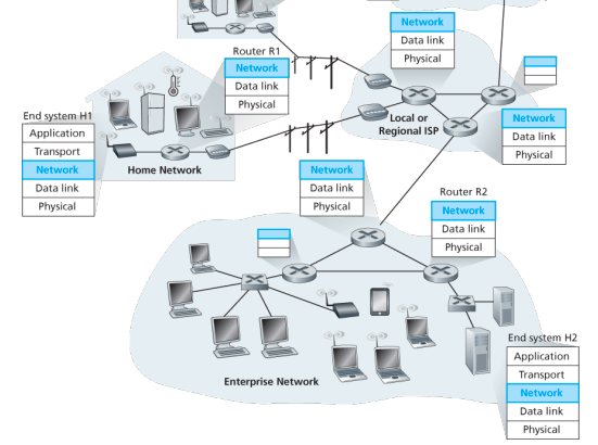
Lets suppose H1 host is sending information to H2 and several routers on the path between H1 and H2. The network layer in H1 takes segments from the transport layer in H1, encapsulates each segment into a datagram, and then sends the datagrams to its nearby router, R1. At the receiving host, H2 the network layer receives the datagrams from its nearby router R2, extracts the transport layer segments, and delivers the segments up to the transport layer at H2.
The primary dataplane role of each router is to forward datagrams from its input links to its output links; primary role of the network control plane is to coordinate these local, per-router forwarding actions so that datagrams are ultimately transferred end-to-end, along paths of routers between source and destination hosts
Forwarding When a packet arrives at a router’s input link, the router must move the packet to appropriate output link. A packet might also be blocked from exiting a router or might be duplicated and sent over multiple outgoing links. Forwarding refers to the router-local action of transfering a packet from an input link interface to the appropriate output link interface, takes place at very short timescales, and thus is typically implemented in hardware.
Routing The network layer must determine the route or path taken by packets as they flow from sender to receiver. A routing algorithm would determine, the path along which packets flow from H1 to H2. Routing refers to network wide process that determines the end-to-end paths that packets take from source to destination, takes place on much longer timescales and is implemented in software
How routing and forwarding are related? Note: A key element in every network router is its forwarding table, a router forwards a packet by examining the value of one or more fields in the arriving packet’s header and then use these header values to index into its forwarding table. The value stored in the forwarding table entry for those values indicates the outgoing link interface at that router to which that packet is to be forwarded. The routing algorithms determines the contents of the routers’ forwarding tables. The routing algorithm function in one router communicates with the routing algorithm function in other routers to compute the values for its forwarding table. A technically feasible case is in which network forwarding tables are configured directly by human network operators physically present at the routers, no routing protocols would be required.
Couldn’t the human approach be modified to be efficient? The approach to implementing routing functionality with each router having a routing component that communicates with the routing component of other routers -has been traditional approach adopted by routing routers. Observation that humans could configure forwarding tables suggest that there are others ways for control-plane functionality to determine the contents of data-plane forwarding tables. An alternate approach is where a physically separate from the routers, remote controller computes and distributes the forwarding tables to be used by each and every router. Remote controller might be implemented in a remote data center with high reliability and redundancy, and might be managed by the ISP or some third party
Network service model
Some possible services that the network layer could provide:
- Guaranteed delivery: The service guarantees that a packet sent by a source host will eventually arrive at the destination host.
- Guaranteed delivery with bounded delay: Not only guarantees delivery of the packet but delivery within a specified host to host delay bound
- In order packet delivery: Guarantees that packets arrive at the destination in the order that they were sent
- Guaranteed minimal bandwidth: Network layer emulates the behavior of a transmission link of a specified bit rate between sending and receiving hosts
- Security: Encrypt datagrams and decrypt them at destination
The Internet’s network layer provides a single service, known as best-effort service, with which, packets are neither guaranteed to be received in the order in which they were sent, nor is their eventual delivery guaranteed. Might appear that best-effort service is a euphemism for no service at all - a network that delivered no packets to the destination would satisfy the definition of best-effort delivery service. For example, the ATM network architecture provides for guaranteed in-order delay, bounded delay, and guaranteed minimal bandwidth.
IPv4 protocol
Two versions of IP in use today.
Key fields of IPv4 packet, referred to as a datagram:
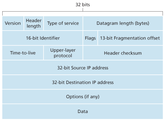
- Version number: These 4 bits specify the IP protocol version of the datagram. By looking at version can determine how to interpret remainder of the IP datagram.
- Header length: Because IPv4 datagram can contain a variable number of options, these 4 bits are needed to determine where in the IP datagram the layer i.e. the transport layer segment being encapsulated actually begins.
- Type of service: Allows different types of IP datagrams to be distinguished from each other. For example it might be useful to distinguish real-time datagrams from non-real traffic.
- Datagram length: This is the total length of the IP datagram (header plus data), measured in bytes. Since this field is 16 bits long, the theoretical maximum size of the IP datagram is 65,535 bytes. However, datagrams are rarely larger than 1,500 bytes, which allows an IP datagram to fit in the payload field of a maximally sized Ethernet frame.
- Identifier, flags, 13-bit fragmentation offset: Have to do with so called IP fragmentation. (later)
- Time-to-live: The TTL field is to ensure that datagrams do not circulate forever, due to, for example, a long lived routing loop in the network. It is decremented by one each time the datagram is processed by a router, if the TTL reaches 0, a router must drop the datagram.
- Protocol: Typically used when an IP datagram reaches its final destination. The value of this field indicates the specific transport-layer protocol to which the data portion of this IP datagram should be passed. For example, a value of 6 indicates that the data portion is passed to TCP, while a value of 17 indicates that the data is passed to UDP.
- Header checksum: Aids a route in detecting bit errors in a received IP datagram. The header is computed by treating each 2 bytes in the header as a number and summing these numbers using 1s complement arithmetic, typically discard when there is checksum error, note that the checksum must be recomputed and stored again at each router, since the TTL filed, and possibility the options field as well, will change.
Why checksum at both TCP and IP? Only header is checksum-ed in IP while whole segment is at TCP, TCP/UDP and IP do not necessairly both have to belong to same protocol stack, TCP can run over a different network layer protocl for example ATM
- Source and destination IP addresses: When a source creates a datagram, it inserts its IP address into the source IP address filed and inserts the address of the ultimate destination into the destination IP address field.
- Options: Allow an IP header to be extended.
- Data (payload): Contains TCP or UDP packets or can carry other types of data such as ICMP messages.
The IP datagram has a total of 20 bytes of header assuming no options, if the datagram carries a TCP segment, then each non-fragmented datagram carries a total of 40 bytes of header (20 bytes of header IP + 20 bytes of TCP header) along with the application-layer messagge.
IPv4 datagram fragmentation
Not all link-layer protocols can carry network-layer packets of the same size. Some protocols can carry big datagrams, whereas other protocols can carry only little datagrams. For example, Ethernet frames can carry up to 1,500 bytes of data, whereas frames for some wide-area links can carry no more than 576 bytes.
The maximum amount of data that a link-layer frame can carry the MTU. Because each IP datagram is encapsulated within the link-layer frame for transport from one router to the next router, the MTU of the link-layer protocol places a hard limit on the length of an IP datagram.
Having a hard limit on the size of an IP datagram is not much of a problem. What is a problem is that each of the links along the route between sender and destination can use different link-layer protocols, and each of these protocols can have different MTUs.
Suppose you receive an IP datagram from one link, you check your forwarding table to determine the outgoing link, and this outgoing link has an MTU that is smaller than the length of the IP datagram. How are you going to squeeze this oversized IP datagram into the payload field of the link-layer frame? The solution is to fragment the payload in the IP datagram into two or more smaller IP datagrams, encapsulate each of these smaller IP datagrams in a separate link-layer frame; and send these frames over the outgoing link. Each of these smaller datagrams is referred to as a fragment.
Fragments need to be reassembled before they reach the transport layer at the destination. Indeed, both TCP and UDP are expecting to receive complete, unfragmented segments from the network layer.
The designers of IPv4 felt that reassembling datagrams in the routers would introduce significant complication into the protocol and put a damper on router performance. Sticking to the principle of keeping the network core simple, the designers of IPv4 decided to put the job of datagram reassembly in the end systems rather than in network routers.
When a destination host receives a series of datagrams from the same source, it needs to determine whether any of these are fragments of some original, larger datagram. If some datagrams are fragments, it must further determine when it has received the last fragment and how the fragments it has received should be pieced back together to from the original datagram. To allow the destination host to perform these reassembly tasks, the designers of IP (version 4) put identification, flag, and fragmentation offset fields in the IP datagram header. When a datagram is created, the sending host stamps the datagram with an identification number as well as source and destination addresses. Typically, the sending host increments the identification number for each datagram it sends. When a router needs to fragment a datagram, each resulting datagram (that is, fragment) is stamped with the source address, destination address, and identification number of the original datagram. When the destination receives a series of datagrams from the same sending host, it can examine the identification numbers of the datagrams to determine which of the datagrams are actually fragments of the same larger datagram. Because IP is an unreliable service, one or more of the fragments may never arrive at the destination. For this reason, in order for the destination host to be absolutely sure it has received the last fragment of the original datagram, the last fragment has a flag bit set to 0, whereas all the other fragments have this flag bit set to 1. Also, in order for the destination host to determine whether a fragment is missing (and also to be able to reassemble the fragments in their proper order), the offset field is used to specify where the fragment fits within the original IP datagram.
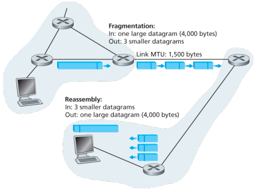
IPv4 and IPv6 differences:
Under IPv4, a router that receives a network packet larger than the next hop’s MTU has two options:
- drop the packet if the Don’t Fragement (DF) flag bit is set in the packet’s header and send an ICMP message which indicates the condition Fragmentation Needed
- or fragment the packet and send it over the link with a smaller MTU
For IPv4 packets, Path MTU Discovery works by setting the DF flag in the IP headers of outgoing packets. Then, any device along the path whose MTU is smaller than the packet will drop it, and send back and ICMP Fragmentation Needed message containing its MTU, allowing the source host to reduce its path MTU approximately. The process is repeated until the MTU is small enough to traverse the entire path without fragmentation..
Although originators may produce fragment packets, IPv6 routers do not have the option to fragment further. Instead, network equipment is required to deliver any IPv6 packets or packet fragements smaller than or equal to 1280 bytes and IPv6 hosts are required to determine the optimal MTU through Path MTU Discovery before sending packets.
As IPv6 routers do not fragment packets, there is DF option in IPv6 header. for IPv6 Path MTU Discovery works by initially assuming the path MTU is the same as the MTU on the link layer interface where the traffic originates. Then, similar to IPv4, any device along the path whose MTU is smaller than the packet will drop the packet and send back an ICMPv6 Packet Too Big message containing its MTU, allowing the source host to reduce its path MTU appropriately.
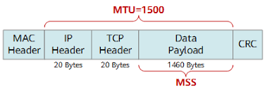 (… some info about addressing here …)
IPv6
The Internet Engineering Task Force began an effort to develop a successor to the IPv4 protocol. A prime motivation for this effort was the realization that the 32-bit IPv4 address space was beginning to be used up, with new subnets and IP nodes being attached to the Internet (and begin allocated unique IP addresses) at a breathtaking rate.
Important changes
- Expanded addressing capabilities: IPv6 increases the size of the IP address from 32 to 128 bits. This ensures that the world won’t run out of IP addresses. Now, every grain fo sand on the planet can be IP-addressable. In addition to unicast and multicast addresses, IPv6 has introduced a new type of address, called an anycast address, that allows a datagram to be delivered to any one of a group of hosts.
- A streamlined 40-byte header: A number of IPv4 fields have been dropped or made optional. The resulting 40-byte fixed-length header allows for faster processing of the IP datagram by a router. A new encoding option allows for more flexible options processing.
- Flow labeling: IPv6 has an elusive definition of a flow. This allows labelling of packets belonging to particular flows for which the sender requests special handling, such as non-default quality of service or real-time service. For example, audio and video transmission might likely be treated as a flow.
No longer present in the IPv6 datagram:
- No hop by hop fragmentation/reassembly: IPv6 does not allow for fragmentation and reassembly at intermediate routers; these operations can be performed only by the source and destination. If an IPv6 datagram received by a router is too large to be forwarded over the outgoing link, the router simply drops the datagram and sends a “Packet Too Big” ICMP error message back to the sender.
- Because the transport-layer (for example, TCP and UDP) and link-layer (for example, Ethernet) protocols in the Internet layers perform checksumming, the designers of IP probably felt that this functionality was sufficiently redundant in the network layer that it could be removed.
- An options field is no longer a part of the standard IP header
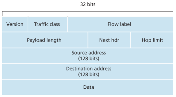
- Version. This 4-bit field identifies the IP version number.
- Traffic class: This 8-bit traffic class field, like the TOS field in IPv4, can be used to give priority to certain datagrams within a flow, or it can be used to give priority to datagrams from certain applications.
- Flow label: This 20-bit is used to identify a flow of datagrams.
- Payload length: This 16-bit value is treated as an unsigned integer giving the number of bytes in the IPv6 datagram following the fixed, 40 byte datagram header.
- Next header: This field identifies the protocol to which the contents (data filed) of this datagram will be delivered (for example, TCP of UDP). When extension header are present in the packet this field indicates which extension header follows.
- Hop limit: The contents of this field are decremented by one by each router that forward the datagram. If the hop limit counts reaches zero, the datagram is discarded.
- Source and destination address
- Data
Extension headers:
Extension headers carry optional internet layer information and are placed between the fixed header and upper-layer protocol header. Extension headers form a chain, using the Next Header fields. The Next Header field in the fixed header indicates the type of the first extension header; Next Header field of the last extension header indicates the type of the upper-layer protocol header in the payload of the packet. All extension headers are a multiple of 8 octets in size; some extension headers require internal padding to meet this requirement.
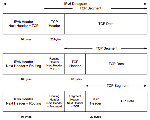
The Fragment header includes the same information as is found in the IPv4 header, but the Identification field is 32 bits instead of the 16 that are used for IPv4. The larger field provides the ability for more fragmented packets to be outstanding in the network simultaneously. The Fragment header uses the format shown in the figure below:
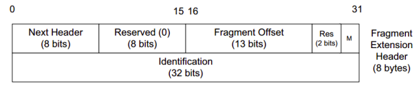
Fragmentation:
Any data link layer conveying IPv6 data must be capable of transmitting an IP packet containing up to 1,280 bytes, thus the sending endpoint may limit its packets to 1,280 bytes and avoid any need for fragmentation or Path MTU Discovery.
A packet containing the first fragment of an original (larger) packet consists of five parts:
- the per-fragment headers (the crucial original headers that are repeatedly used in each fragment)
- followed by the Fragment extension header containing a zero Offset
- then all the remaining original extension headers
- then the original upper-layer header (alternatively the ESP header)
- and a piece of the original payload.
Each subsequent packet consists of three parts:
- the per-fragment headers,
- followed by the Fragment extension header,
- and by a part of the original payload as identified by a Fragment Offset.
The original packet is reassembled by the receiving node by collecting all fragments and placing each fragment at its indicated offset and discarding the Fragment extension headers of the packets that carried them. Packets containing fragments need not arrive in sequence; they will be rearranged by the receiving node.
Example:
The following example illustrates the way an IPv6 source might fragment a datagram:
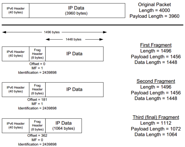
A payload of 3960 bytes is fragmented such that no fragment’s total packet size exceeds 1500 bytes (a typical MTU for Ethernet), yet the fragment data sizes still are arranged to be multiples of 8 bytes.
- A 2960-byte payload is split into three fragment packets of size 1448 bytes or less.
- The Fragment header in each fragment contains a common Identification field.
- All but the last fragment have the More fragments field (M) set to 1. The offset is given in 8 byte units - the last fragment, for example, contains data beginning at offset bytes from the beginning of the original packet’s data. The scheme is similar to fragmentation in IPv4.
- The IPv6 header’s Payload Length field is modified to reflect the size of the data and newly formed Fragment header.
IPv6 Addressing
IPv6 addresses are classified by the primary addressing and routing methodologies common in networking:
- unicast addressing,
- anycast addressing,
- multicast addressing,
A unicast address identifies a single network interface. The IP delivers packets sent to a unicast address to that specific interface.
An anycast address is assigned to a group of interfaces, usually belonging to different nodes. A packet sent to any anycast address is delivered to just one of the member of interfaces, typically the nearest host, according to the routing protocol’s definition of distance. Anycast addresses cannot be identified easily, they have the same format as unicast addresses, and differ only by their presence in the network at multiple points. Almost any unicast address can be employed as an anycast address.
A multicast address is also used by multiple hosts that acquire the multicast address destination by participating in the multicast distribution protocol among the network users. A packet that is sent to a multicast address is delivered to all interfaces that have joined the corresponding multicast group. IPv6 does not implement broadcast addressing.
Addressing:
Anycast addresses are syntactically identical to and indistinguishable from unicast addresses. Their only difference is administrative. Scopes for anycast addresses are therefore the same as for unicast addresses.
For multicast addresses, the four least-significant bits of the second address octet (ff0s::) identify the address scope, i.e. the domain in which the multicast packet should be propagated.
Unicast and anycast addresses are typically composed of two logical parts: a 64-bit network prefix used for routing and a 64-bit interface identifier used to identify a host’s network interface.
Networks
An IPv6 network uses an address block that is contiguous group of IPv6 addresses of size that is a power of two. The leading set of bits of the addresses are identical for all hosts in a given network, and are called the network’s address or routing prefix. Network address ranges are written in CIDR notation. A network is denoted by the first address in the block (ending in all zeroes), a slash (/), and a decimal value equal to the size in bits of the prefix. For example, the network written as 2001:db8:1234::/48 starts at address 2001:db8:1234:0000:0000:0000:0000:0000 and ends at 2001:db8:1234:ffff:ffff:ffff:ffff:ffff. The routing prefix of an interface address may be directly indicated with the address using CIDR notation. For example, the configuration of an interface with address 2001:db8:a::123 connected to subnet 2001:db8:a::/64 is written as 2001:db8:a::123/64.
Address space:
The management of IPv6 is delegated to IANA by the IAB. Its main function is the assignment of large address blocks to RIRs, which have the delegated task of allocation of network service providers and other local registries. The IANA has maintained the official list of allocations of the IPv6 address space since December 1995.
- In order to allow efficient route aggregation, thereby reducing the size of the Internet routing tables, only one-eight of the total address space (
2000::/3) is currently allocated for use on the Internet. The rest of the IPv6 address space is reserved for the future use or for special purposes. - The address space is assigned to RIRs in blocks of /23 up to /12.
- The RIRs assign smaller blocks to local Internet registries that distribute them to users. These are typically in sizes from /19 to /32. Global unicast assignment can be found at the various RIRs or other websites.
- The addresses are then typically distributed in /48 to /56 sized blocks to the end users. IPv6 addresses are assigned to organizations in much larger blocks as compared to IPv4 address assignments—the recommended allocation is a /48 block which contains addresses, being times larger than the entire IPv4 address space of addresses.
Here, each RIR can divide each of its multiple blocks into 512 /32 blocks, typically one for each ISP; an ISP can divide its /32 block into 65536 /48 blocks, typically one for each customer, customers can create 65536 /64 networks from their assigned /48 block, each having addresses.
Special allocation:
Provider independent address space is assigned directly to the end user by the RIRs from the special range 2001:678::/29 and allows customers to make provide changes without renumbering their networks.
(someabout about IXPs and Root name servers)
Transition to IPv6
Already deployed IPv4-capable systems are not capable of handing IPv5 datagrams. One option would be to declare a flag day - a given time and date when all Internet machines would be turned off and upgraded from IPv4 to IPv6. Last major transition was from using NCP to TCP almost 35 years ago.
The approach to IPv4 to IPv6 that has been widely adopted in practice involves tunneling.
Suppose two IPv6 nodes want to interoperate using IPv6 datagrams but are connected to each other by intervening IPv4 routers. We refer to the intervening set of IPv4 routers between two IPv6 routers as a tunnel. With tunneling, the IPv6 node on the sending side of the tunnel takes the entire IPv6 datagram and puts it in the data (payload) field of an IPv4 datagram. This IPv4 datagram is then addressed to IPv6 node on the receiving side of the tunnel. The intervening IPv4 routers in the tunnel router this IPv4 datagram among themselves, just as though would any other datagram, blissfully unaware that the IPv4 datagram itself contains a complete IPv6 datagram. The IPv6 node on the receiving side of the tunnel eventually receives the IPv4 datagram (it is the destination of the IPv4 datagram!), determines that the IPv4 datagram contains an IPv6 datagram (by observing that the protocol number field in the IPv4 datagram is 41, indicating that the IPv4 payload is a IPv6 datagram), extracts the IPv6 datagram, and then routes the IPv6 datagram exactly as it would if it had received the IPv6 datagram from a directly connected IPv6 neighbor. …
Dual Stack:
allow IPv4 and IPv6 to coexist in the same devices and networks
…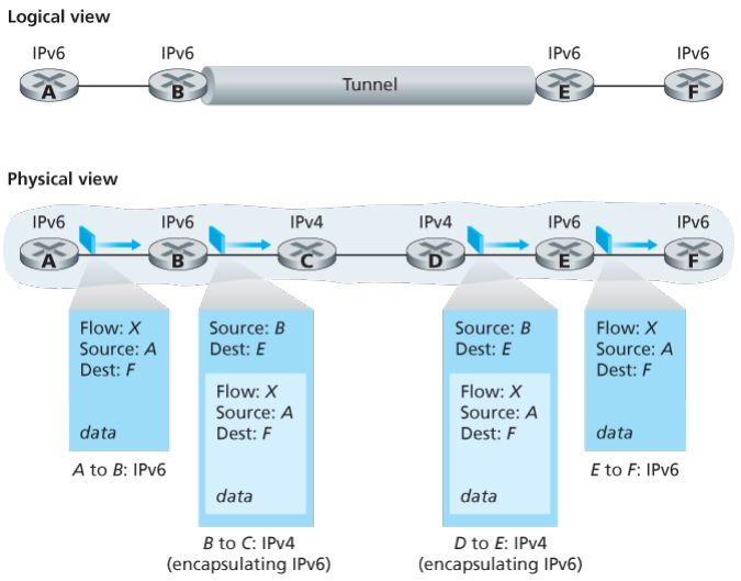 ..
..
(the internet layer would include routing algos, other protocols and all those stuffs then only MPLS)
Multiprotocol Label Switching (MPLS)
MPLS evolved from a number of industry efforts in the mid-to-late 1990s to improve the forwarding speed of IP routers by adopting a key concept from the world of virtual-circuit networks: a fixed-length label. The goal was not to abandon the destination based IP datagram forwarding infrastructure for one based on fixed length labels and virtual circuits, but to augment it by selectively labeling datagrams and allowing routers to forward datagrams based on fixed length labels (rather than destination IP addresses) when possible .
Importantly, these techniques work hand-in-hand with IP, using IP addressing and routing. The IETF united these efforts in the MPLs protocol, effectively bending VC techniques into a routed datagram network.
For connection-oriented service, we need a virtual-circuit network. The idea behind virtual circuits is to avoid having to choose a new route for every packet sent. Instead, when a connection is established, a route from the source machine to the destination machine is chosen as part of the connection setup and stored in tables inside the routers. That route is used for all traffic flowing over the connection, exactly the same way that the telephone system works. When the connection is released, the virtual circuit is also terminated. With connection-oriented service, each packet carries an identifier telling which virtual circuit it belongs to.
In some context, this process is called label switching. An example of a connection-oriented network service is MPLS (MultiProtocol Label Switching). It is used within ISP networks in the Internet, with IP packets wrapped in an MPLS header having a 20-bit connection identifier or label. MPLS is often hidden from customers, with the ISP establishing long-term connections for large amounts of traffic, but it is increasingly being used to help when quality of service is important but also with other ISP traffic management tasks
How MPLS works?
- MPLS adds a label in front of each packet, and forwarding is based on the label rather than on the destination address. Making the label an index into an internal table makes finding the correct output line just a matter of table lookup. Using this technique, forwarding can be done very quickly.
- The first question to ask is where does the label go? Since IP packets were not designed for virtual circuits, there is not field available for virtual-circuit numbers within the IP header. For this reason, a new MPLS header had to be added in front of the IP header.
- The generic MPLS header is 4 bytes long and has four fields. Most important is the Label field, which holds the index. The QoS field indicates the class of service. The S field relates to stacking multiple labels. The TtL field indicates how many more times the packet may be forwarded. It is decremented at each router, and if it hits 0, the packet is discarded. This feature prevents infinite looping in the case of routing instability.
- How the label forwarding tables are set up so that packets follow them? In traditional virtual-circuit networks, when a user wants to establish a connection, a set up packet is launched into the network to create the path and make the forwarding table entries. MPLS does not involve users int he setup phase. Requiring users to do anything other than send datagram would break too much existing Internet software. Instead, the forwarding information is set up by protocols that are a combination of routing protocols and connection setup protocols. These control protocols are cleanly separated from label forwarding, which allows multiple, different control protocols to be used. One of the variants works like this. When a router is booted, it checks to see which routes it is the final destination for (e.g., which prefixes belong to its interfaces). It then creates one or more FECs for them, allocates a label for each one, and passes the labels to its neighbors. They, in turn, enter the labels in their forwarding tables and send new labels to their neighbors, until all the routers have acquired the path.
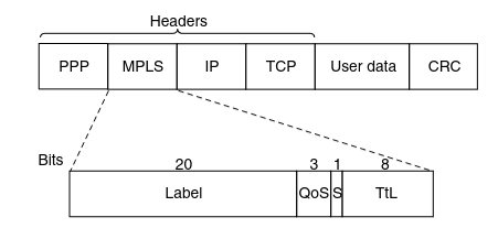
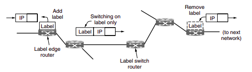
Since most hosts and routers do not understand MPLS, we should also ask when and how the labels are attached to packets. This happens when an IP packet reaches the edge of an MPLS network. The Label Edge Router inspects the destination IP address and other fields to see which MPLS path the packet should follow, and puts the right label on the front of the packet. Wihin the MPLS network, tthis label is sued to forward the packet. At the other edge, of the MPLS network, the label has served its purpose and is removed, releaving the IP packet again for the next network.
Other Application Layer Protocols
FTP
In a typical FTP session, the user is sitting in front of one host (the local host) and wants to transfer files to or from a remote host. In order for the user to access the remote account, the user must provide a user identification and a password.
After providing this authorization information, the user can transfer files from the local file system to the remote file system and vice versa.
The user interacts with FTP through an FTP user agent. The user first provides the hostname of the remote host, causing the FTP client process in the local host to establish a TCP connection with the FTP server process in the remote host. The user then provides the user identification and password, which are sent over the TCP connection as part of FTP commands.
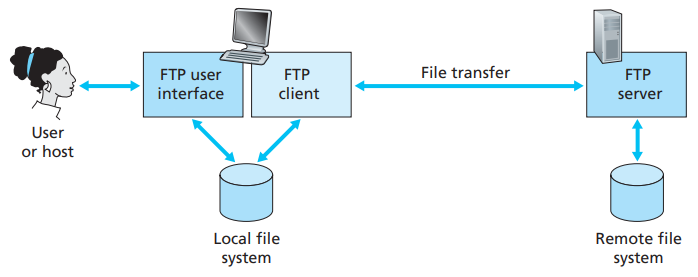 Once the server has authorized the user, the user copies one or more files stored in the local file system into the remote file system (or vice versa).
HTTP and FTP are both file transfer protocols and have many common characteristics; for example, they both run on top of TCP. However, the two application-layer protocols have some important differences. The most striking difference is that FTP uses two parallel TCP connections to transfer a file, a control connection and a data connection.
The control connection is used for sending control information between the two hosts—information such as user identification, password, commands to change remote directory, and commands to “put” and “get” files.
The data connection is used to actually send a file. Because FTP uses a separate control connection, FTP is said to send its control information out-of-band.
- When a user starts an FTP session with a remote host, the client side of FTP (user) first initiates a control TCP connection with the server side (remote host) on server port number 21.
- The client side of FTP sends the user identification and password over this control connection. The client side of FTP also sends, over the control connection, commands to change the remote directory.
- When the server side receives a command for a file transfer over the control connection (either to, or from, the remote host), the server side initiates a TCP data connection to the client side.
- FTP sends exactly one file over the data connection and then closes the data connection. If, during the same session, the user wants to transfer another file, FTP opens another data connection.
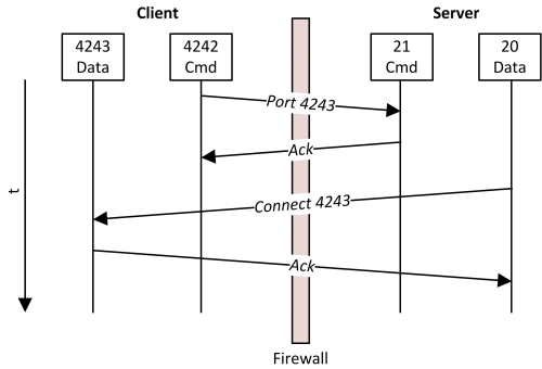
Throughout a session, the FTP server must maintain state about the user. In particular, the server must associate the control connection with a specific user account, and the server must keep track of the user’s current directory as the user wanders about the remote directory tree.
The commands, from client to server, and replies, from server to client, are sent across the control connection in 7-bit ASCII format. Thus, like HTTP commands, FTP commands are readable by people. In order to delineate successive commands, a carriage return and line feed end each command. Each command consists of four uppercase ASCII characters, some with optional arguments. Some of the more common commands are given below:
- USER username
- PASS password
- LIST:
- RETR filename
- STOR filename
There is typically a one-to-one correspondance between the command that user issues and the FTP command sent across the control connection. Each command is followed by a reply, sent from server to client. The replies are three-digit numbers, with an optional message following the number.
Types of FTP:
From a networking perspective, the two main types of FPT are active and passive. In active FTP, the FTP server initiates a data transfer connection back o the client. For passive FTP, the connection is initiated from the FTP client.
From a user management perspective, there are two additional types of FTP: regular FPT, in which files are transferred using the username and password of a regular user FTP server, and anonymous FTP, in which general access is provided to the FTP server using a well known universal login method.
Regular FTP:
By default, the VSFTPD package allows regular Linux users to copy files to and from their home directories with an FPT client using their Linux usernames and passwords as their login credentials.
Electronic mail
Email is an asynchronous communication medium -people send and read messages when it is convenient for them, without having to coordinate with other people’s schedules. In contrast with postal mail, electronic mail is fast, easy to distribute, and inexpensive.
The high-level view of Internet mail system has three major components: user agents, mail servers, and the Simple Mail Transfer Protocol (SMTP).
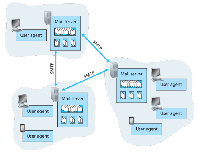
User agents allow users to read, reply to, forward, save, and compose messages such as Outlook and Apple Mail.
When Alice is finished composing her message, her user agent sends the message to her mail server, where the message is placed in the mail server’s outgoing message queue. When Bob wants to read a message, his user agent retrieves the message from his mailbox in his mail server
Each recipient such as Bob, has a mailbox located in one of the mail server. A typical message starts its journey in the sender’s user agent, travels to the sender’s mail server, and travels to the recipient’s mail server, where it is deposited in the recipient’s mailbox.
When Bob wants to access his mailbox, the mail server containing his mailbox authenticates Bob with usernames and passwords. Alice’s mail server must also deal with failures in Bob’s mail server. If Alice’s server cannot deliver mail to Bob’s server, Alice’s server holds the message in a message queue and attempts to transfer the message later.
Reattempts are often done every 30 minutes or so; if there is no success after several days, the server removes the message and notifies the sender with an e-mail message.
SMTP is the principal application-layer protocol which uses reliable service of TCP to transfer mail from the server’s mail server to recipient’s mail server.
SMTP is much older than HTTP. SMTP has two sides: a client side, which executes on the sender’s mail server, and a server side, which executes on the recipient’s mail server.
Although SMTP has numerous wonderful qualities, as evidenced by its ubiquity in the Internet, it is nevertheless a legacy technology that possesses certain archaic characteristics. For example, it restricts the body not just the headers of all mail messages to simple 7-bit ASCII. While HTTP does not require multimedia data to be ASCII encoded before transfer.
It is important to observe that SMTP does not normally use intermediate mail servers for sending mail, even when the two mail servers are located at opposite ends of the world. In particular, even if one server is down, the message remains in the sender’s mail server and waits for a new attempt - the message does not get placed in some intermediate mail server.
Process:
Example: An transcript of messages exchanged between an SMTP client (C) and an SMTP server (S), the hostname of the client is crepes.fr and the hostname of the server is hamburger.edu, the following ASCII text lines prefaced with C: are exactly the lines the client sends into its TCP socket, and the ASCII text lines prefaced with S: are exactly the lines the server sends into its TCP socket:
-
Server opens TCP connection with receiver. Once connected, receiver identifies itself. Sender identifies itself. Receiver accepts sender’s identification.
S: 220 hamburger.edu C: HELO crepes.fr S: 250 Hello crepes.fr, pleased to meet you -
The MAIL FROM command identifies the originator. Receiver returns 250 OK or appropriate failure message. One or more RCPT TO command identify recipients for the message. The DATA command transfers the message text.
C: MAIL FROM: <alice@crepes.fr> S: 250 alice@crepes.fr ... Sender ok C: RCPT TO: <bob@hamburger.edu> S: 250 bob@hamburger.edu .. Receipt ok C: DATA S: 354 Enter mail, end with "." on a line by itself C: Do you like ketchup? C: How about pickles? C: . S: 250 Message accepted for delivery -
Sender sends QUIT and waits for reply. Then initiate TCP close connection.
 C: QUIT
 S: 221 hamburger.edu closing connection
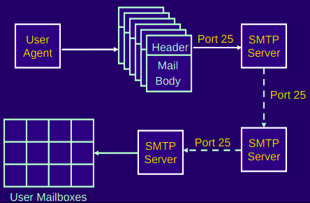
Comparison with HTTP:
When transferring the files, both persistent HTTP and SMTP use persistent connections. First HTTP is mainly a pull protocol. Someone loads information on a Web server and users use HTTP to pull the information from the server at their convenience, in particular, the TCP connection is initiated by the machine that wants to receive the file. On the other hand, SMTP is primarily a push protocol - the sending mail server pushes the file to the receiving mail server. A second difference is that SMTP requires each message, including the body of each message to be in 7-bit ASCII format, if does not or contains binary then the message has to be encoded into 7-bit ASCII. HTTP encapsulates each object in its own HTTP response message, SMTP places all of the message’s objects into one message.
When an email message is sent from one person to another, a header containing peripheral information precedes the body of the message itself, is contained in a series of header lines. As with HTTP, each header line contains readable text, consisting of a keyword followed by a colon followed by a value. The header lines and the body of the message are separated by a blank line CRLF. Every header must have a From: header line and and a To: header line; a header may include a Subject: header line as well as other optional header lines. Those header lines are different from SMTP commands, where were part of the SMTP handshaking protocol; the header lines here are part of the mail message itself. After the message header, a blank line follows; then the message body in ASCII follows
Mail Access Protocols:
Once SMTP delivers the message from Alice’s mail server to Bob’s mail server, the message is placed in Bob’s mailbox. Up until early, Bob reads his mail by logging onto the server host and then executing a mail reader that runs on that host.
But today, mail access uses a client-server architecture -the typical user reads e-mail with a client that executes on the user’s end system. By executing a mail client on a local PC, users enjoy a rich set of features, including the ability to view multimedia messages and attachments.
To send email messages from Alice’s user agent to Alice’s mail server, can simply be done with SMTP indeed SMTP has been designed for pushing email from one host to another.
Alice’s user agent uses SMTP to push the email message into her mail server, then Alice’s mail server uses SMTP as an SMTP client to relay the email message to Bob’s server.
But there is still one missing piece to the puzzle? How does a recipient like Bob, running a user agent on his local PC, obtain his messages, which are sitting in a mail server within Bob’s ISP? The Bob’s user agent cant use SMTP to obtain messages because obtaining the messages is a pull operation, whereas SMTP is a push protocol.
The puzzle is completed by introducing a special access protocol that transfers messages from Bob’s mail server to his local PC including POP3, IMAP, and HTTP.
POP3
POP3 is an extremely simple mail access protocol which is short and quite readable. Because the protocol is simple, it functionality is rather limited. POP3 begins when the user agent (the client) opens a TCP connection to the mail server on port 110.
With the TCP connection established, POP3 progresses through three phases: authorization, transaction, and update.
- During the first phase, authorization, the user agent sends a username and a password in the clear to authenticate the user.
- During the second phase, transaction, the user agent retrieves messages; also during which, the user agent can mark messages for deletion, remove deletion marks, and obtain mail statistics. A user agent using POP3 can often be configured to download and delete or download and keep. In the download-and-delete, mode the user will issue the list, retr and dele commands.
- The third phase, update, occurs after the client has issued the quit command, ending the POP3 session; at this time, the mail server deletes the messages that were marked for deletion.
In a POP3 transaction, the user agent issues commands, and the server responds to each command with a reply, are two possible responses: +OK (sometimes followed by server-to-client data), used by the server to indicate that ther previous command was fine; and -ERR, used by the server to indicate that something was wrong with the previous command.
A problem with this download-and-delete mode is that the recipient, Bob, may be nomadic and may want to access his mail messages from multiple machines, for example, his office PC, home PC. The download-and-delete mode partitions Bob’s mail messages over these three machines; in particular, if Bob first reads a message on his office PC, he will not be able to reread the message from his portable at home later in the evening. In the download-and-keep mode, the user agent leaves the messages on the mail server after downloading them. In this case, Bob can reread messages from different machines; he can access a message from work and access it again later in the week from home.
IMAP
POP3 does not provide any means for a user to create remote folders and assign messages to folders. To solve this and other problems, the IMAP, protocol was invented. Like POP3, IMAP is an mail access protocol. It has many more features than POP3 and is also significantly more complex to implement.
- An IMAP server will associate each message with a folder; when a message first arrives at the server, it is first associated with the recipient’s INBOX folder. The recipient can then move message into a new user-created folder, read the message, delete and so on.
- A user can check the email header before downloading.
- The IMAP protocol provides commands to commands that permit a users obtain components of messages, for ex: a user agent can obtain just the message header of a message or just one part of a multipart MIME message. This feature is useful when there is a low-bandwidth connection between the user agent and its mail server.
| Feature | POP (Post Office Protocol) | IMAP (Internet Message Access Protocol) |
|---|---|---|
| Definition | A protocol designed to download emails from the server to a single computer. | A protocol designed for accessing email on a remote server from multiple devices. |
| Suitability | Best for accessing mail from a single device. | Ideal for accessing your mail from multiple devices or locations. |
| Compatibility | Supported by all mail clients. | Supported by most mail clients, with added web access functionality. |
| Checking Incoming Mail | Incoming messages are downloaded to the local machine; seen only on that device unless configured otherwise. | Messages stay on the server; headers are downloaded, and full messages are fetched on demand. Accessible from any device. |
| Reading and Responding to Mail | Actions are performed on the local machine. | Actions can be performed on the server or locally, with changes synced across devices. |
| Creating Mailboxes | Mailboxes for storing messages are created locally. | Mailboxes are created on the server, allowing consistent access across devices. |
| Managing Messages | Moving messages between mailboxes is restricted to the local device. | Messages can be moved freely between server and local mailboxes, offering flexibility. |
| Message Transfer | Direct server upload is not supported; messages are primarily downloaded. | Supports transferring messages between the server and local storage, offering greater control. |
| Deleting Messages | Limited server interaction; deleting may only remove the local copy if configured to keep server copies. | Direct and flexible management of message deletion on both the server and local device. |
Web-based email:
With web based emails, the user cagent communicates with its remote mailbox via HTTP. When a sender, such as Alice, wants to send an email message, the email message is sent from her browser to her mail server over HTTP rather than over SMTP. Alice’s mail server, however, still sends messages to, and receives messages from, other mails servers using SMTP.
MIME
MIME is an internet standard that extends the format of email messages to support text in character sets other than ASCII, as well as attachments of audio, video, images and application programs. Email messages with MIME formatting are typically transmitted with standard protocols, such as SMPT, POP and the IMAP.
MIME headers:
- MIME-Version
- Content-Type: incidates the media type of the message content, consisting of type and subtype
- Content-Transfer-Encoding: MIME defines a set of methods for representing binary data in formats other than ASCII text format.
PGP
PGP is an encryption program that provides cryptographic privacy and authentication for data communication. PGP is used for signing, encrypting, and decrypting texts, emails, files, directories, and whole disk partitions and to increase the security of email communications. Although PGP can be used for protecting data in long term storage, it is used primarily for email security.
PGP encryption uses a serial combination of hashing, data compression, symmetric key cryptography and public-key cryptography; each step uses one of several supported algorithms. Each public key is bound to a username or an email address.
PGP’s operation consists of five services:
-
Authentication service. Sender authentication consists of the sender attaching his/her signature to the email and the receiver verifying the signature using pubic-key cryptography. Here is an example of authentication operations carried out by the sender and the receiver:
- At the sender’s end, the SHA-1 hash functions is used to create a 160-bit message digest of the email message..
- The message digest is encrypted with RSA using the sender’s private key and the result is prepended to the message. The composite message is transmitted to the recipient.
- The receiver uses RSA with the sender’s public key to decrypt the message digest.
- The receiver compares the locally computed message digest with the received message digest. Due to the strength of RSA the recipient is assured that only the possesor of the matching private key can generate the signature. Because of the strength of SHA-1 the recipient is assured that no on else could generate a new message that matches the hash code and hence, the signature of the original message.
-
Confidentiality service: The 128-bit encryption key called the session is generated for each messages separately. The message is encrypted using CAST-128, IDEA or 3DES with the session key. The session key is encrypted with RSA using the recipients public key and is pre-pended to the message.
-
Compression: By default PGP compresses the email message after appending the signature but before encryption. This makes long-term storage of messages and their signatures more efficient. This also decouples the encryption algorithm from the message verification procedures. Compression is carried out with the ZIP algorithm.
-
Email compatibility service: Many electronic mail systems only permit the use of blocks consisting of ASCII text. When PGP is used, at least part of the block to be transmitted is encrypted. This basically produces a sequence of arbitrary binary words which some mail systems won’t accept. To accommodate this restriction PGP uses and algorithm known as radix64 which maps 6 bits of a binary data into and 8 bit ASCII character.
-
Segmentation service: E-mail facilities are often restricted to a maximum message length. For example, many of the facilities accessible throughout the Internet impose a maximum length of 50,000 octets. Any message longer than that must be broken up into smaller segments, each of which is mailed separately.
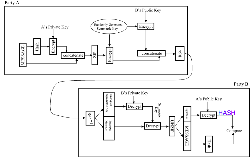
Designing Internet Systems and Servers
What was a server again?
A server is a piece of computer hardware or software that provides functionality for other programs or devices, called clients. The role of a server is to share data as well as to share resources and distribute work. The following are several scenarios in which a server is used:
-
Web server: Hosts web pages. A web server is what makes WWW possible. Each website has one or more web servers. Also, each serer can host multiple websites.
-
Mail server: Makes email communication possible in the same way that a post office makes snail mail communication possible.
-
Proxy server: Acts as an intermediary between a client and a server, accepting incoming traffic from the client and sending it to the serer. Reasons for doing so include content control and filtering, improving traffic performance, preventing unauthorized network access or simply routing traffic over a large and complex network.
DHCP server?
RADIUS server:
RADIUS (Remote Authentication Dial In User Service) is a networking protocol that provides centralized authentication, authorization, and accounting services for users who connect and use network services. The point at which the user connects to the network is known as the Network Access Server (NAS), while user authentication and account information is stored in a database on the RADIUS server. The RADIUS protocol is used to communicate between the NAS and RADIUS server.
When a user connects to the network, the NAS challenges the user for authentication, and pass on the authentication to the RADIUS server to check. Based on the result of the check against the user database, the RADIUS server informs the NAS whether or not to allow the connected user access to the network.
A RADIUS server can do more than allow or deny access to the network. A RADIUS server can send back parameters to the connected users, such as an IP address for the user, or a VLAN for the user, or a privilege level for a session. RADIUS also provides an accounting service. Switches can inform the RADIUS server how long a user has been connected to the network, and how much traffic the user has sent and received while connected to the network.
-
Authentication determines the identity of the user and whether the user has appropriate permissions to access the resource to which it is requesting access. This is accomplished by matching the credentials such as username and password, digital certificates, short duration validity passwords called One Time Passwords (OTP), generated by (OTP) tokens to user’s profile.
-
Authorization involves determining what authenticated users are allowed to do.
-
Accounting involves tracking usage during the lifetime of connection.
The original use for RADIUS was for the authentication of users dialing into an ISP (Internet Service Provider). A PPP (Point-to-Point Protocol) connection would be established between the remote client and the ISP’s access switch. The ISP’s access switch would receive the client’s username and password using PAP (Password Authentication Protocol) or using CHAP (Challenge Handshake Authentication Protocol) and pass on the client’s username and password to the RADIUS server to authenticate the client. The RADIUS server’s response to the authentication request would be sent back to the client as a PAP or CHAP allow or deny.
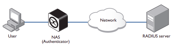
A RADIUS exchange is initiated by the NAS when a user requests access to the NAS. The NAS obtains the user authentication data adds them into a RADIUS Access-Request packet type and sends the RADIUS Access-Request packet to the RADIUS server.
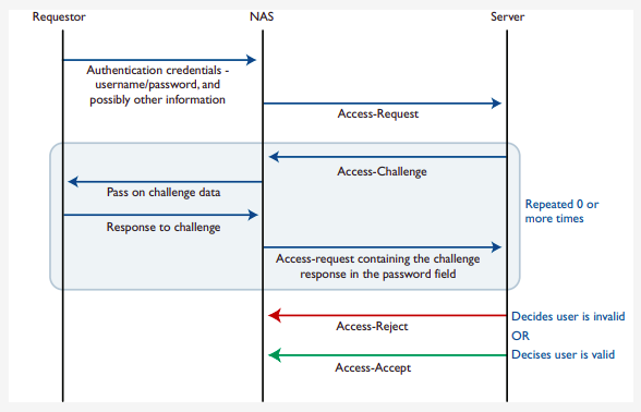
Proxy servers
A proxy server is a server application that acts as an intermediary between a client requesting a resource and the server providing that resource. It improves privacy, security, and performance in the process. Instead of connecting directly to a server that can fulfill a request for a resource, such as file or web page, the client directs the request to the proxy server, which evaluates the request and performs the required network transactions.
A proxy server may reside on the user’s local computer, or at any point between the user’s computer and destination servers on the Internet. A proxy server that passes unmodified requests and responses is usually called a gateway or sometimes a tunneling proxy.
- A forward proxy is an Internet facing proxy used to retrieve data from a wide range of sources (in most cases, anywhere on the Internet).
- A reverse proxy is usually an internal-facing proxy used as a front-end to control and protect access to a serer on a private network. A reverse proxy also commonly performs tasks such as load-balancing, authentication, decryption and caching.
Open proxies:
An open proxy is a forwarding proxy server that is accessible by any Internet user.
- Anonymous proxy: This server reveals its identity as a proxy server but does not disclose the originating IP address of the client. Although this type of server can be discovered easily, it can be beneficial for some users as it hides the originating IP address.
- Transparent proxy: This server not only identifies itself as a proxy serer but with the support of HTTP header fields, the originating IP address can be retrieved as well. The main benefit of using this type of server is its ability to cache a website for faster retrieval.

Reverse proxies:
A reverse proxy (or surrogate) is a proxy server that appears to clients to be an ordinary server. Reverse proxies forward requests o one or more ordinary servers that handle the request. The response from the original server is returned as if it came directly from the proxy server, leaving the client with no knowledge of the original server. Reverse proxies are installed on the vicinity of one or more web servers. All traffic coming from the Internet and with a destination of one of the neighborhood’s web servers goes through the proxy servers. The use of reverse originates in its counterpart forward proxy since the reverse proxy sits closer to the web server and serves only a restricted set of websites.
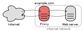
There are several reasons for using proxy servers:
- Encryption/SSL acceleration
- Load balancing
- Serve/cache static content
- Compression
- Spoon feeding
- Security
- Extranet publishing: a reverse proxy server facing the Internet can be used to communicate to a firewall server internal to an organization providing extranet access to some functions while keeping the servers behind the firewalls. If used in this way, security measures should be considered to protect the rest of your infrastructure in case this server is compromised, as its web application is exposed to attack from the Internet.
Load balancing
Load balancing is the practice of distributing computational workloads between two or more computers. On the Internet, load balancing is often employed to divide network traffic among several servers. This reduces the strain on each server and makes the servers more efficient, speeding up performance and reducing latency. Load balancing is essential for most Internet applications to function properly.
Round robin DNS: is a technique of load distribution, load balancing, or fault tolerance provisioning multiple, redundant IP service hosts, e.g. Web server, FTP servers, by managing the DNS responses to address requests from client computers according to an appropriate statistical model. In its simplest implementation, round-robin DNS works by responding to DNS requests not only with a single potential IP address, but with a list of potential IP addresses corresponding to several servers that host identical services.
-
Although easy to implement, round-robin DNS has a number of drawbacks, such as those arising from record caching in the DNS hierarchy itself, as well as client-side address caching and reuse, the combination of which can be difficult to manage.
-
May not be best choice for load balancing on its own, since it merely alternates the order of the address records each time a name server is queried. Because it does not take transaction time, server load, and network congestion into consideration, it works best for services with a large number of uniformly distributed connections to servers of equivalent capacity.
Internet Cache Protocol (ICP): is a UDP based protocol for coordinating web caches. Its purpose is to find out the most appropriate location to retrieve a requested object in the situation where multiple caches are in use at a single site. To retrieve a requested object in the situation where multiple caches are in use at a single site:
Operation:
- Hierarchically, a queried cache can either be a parent or a sibling
- Parents usually sit closer to the internet connection than the child. If a child cache cannot find an object, the query usually will be sent to the parent cache, which will fetch, cache, and pass on the request. Siblings are caches of equal hierarchical status, whose purpose is to distribute the load amongst the siblings.
- When a request comes into one cache in a cluster of siblings, ICP is used to query the siblings for the object being requested. If the sibling has the object, it will usually be transferred from there, instead of being queried from the original server. This is often called a “near miss” — the object is not found in the cache (a “miss”) but is loaded from a nearby cache, instead of from a remote server.
 Bad: Generates extra network traffic, more proxy servers = more querying, caches become redundant, duplication
Cache Array Routing Protocol: CARP is an array containing multiple servers that can act as a single logical cache. The CARP is used in load balancing HTTP requests across multiple proxy cache servers. It works by generating a hash for each URL requested. A different hash is generated for each URL and by splitting the hash namespace into equal parts (or unequal parts if uneven load is intended) the overall number of requests can be distributed to multiple servers.
With the CARP, an array containing multiple servers can act as a single logical cache.
- Because CARP determines the best request resolution path, there is no query messaging between proxy servers in an array, as is found with conventional Internet Cache Protocol (ICP) networks. By doing this, CARP avoids the heavier query congestion that normally occurs with a greater number of servers.
- CARP eliminates the duplication of content that otherwise occurs on an array of proxy servers. With an ICP network, an array of five proxy servers can rapidly evolve into duplicate caches of the most frequently requested objects. The hash-based routing of CARP keeps this from happening by allowing all five Forefront TMG servers to exist as a single logical cache. The result is a faster response to queries and a far more efficient use of server resources.
- CARP has positive scalability. Due to its hash-based routing and its resultant independence from peer-to-peer pinging, CARP becomes faster and more efficient as more proxy servers are added. ICP arrays must conduct queries to determine the location of cached information. This is an inefficient process that generates extraneous network traffic. ICP arrays have negative scalability: the more servers added to the array, the more querying required between servers to determine location.
- CARP automatically adjusts to additions or deletions of servers in the array. The hash-based routing means that, when a server is either taken offline or added, only minimal reassignment of caches for specific URLs is required.
- CARP ensures that the cached objects are either distributed evenly between all servers in the array or by the load factor that you configure for each server.
How CARP works?
- (looks complicated but here is a simple one)
- A hash value is computed for the name of each proxy server in the list (only when list changes). Similarly, a hash value is computed for the name of each requested URL. For each request, a combined hash value is computed for all servers. Use highest to select one.
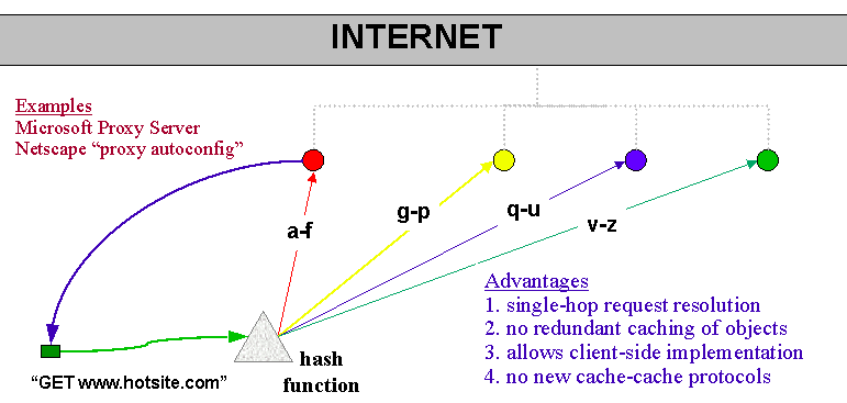
CARP scalability (when you add new proxy):
Before:
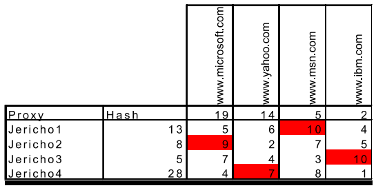
After:
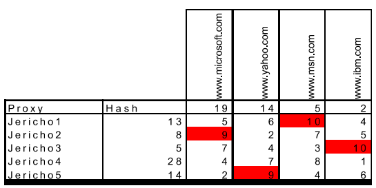
CARP exceptions:
Some websites require that client IP addresses remain unchanged throughout a session. Requests should be sent to these Web sites without using the CARP algorithm.
Web server configurations
The Apache HTTP server is a free and open source cross platform web server software, released under the terms of Apache License 2.0. The vast majority of Apache HTTP Server instances run on Linux distribution but current versions also run on Microsoft Windows, and a wide variety of Unix-like systems.
Apache supports a wide variety of features, many implemented as compiled modules which extend the core functionality. These can range from authentication schemes to supporting server-side programming langauges.
Apache Web Server features include:
- Support for server-side programming languages (Perl, PHP, Python)
- Authentication modules (mod_access, mod_auth, mod_digest, mod_auth_digest)
- SSL/TLS support (mod_ssl)
- Proxy module
- URL rewriting
- Custom log files
- Virtual hosting
- Log analysis
- Scalability (handles more than 10,000 simultaneous connections)
The primary Apache configuration file is /etc/httpd/conf/httpd.conf. It contains a lot of configuration statements that don’t need to be changed for a basic installation. In fact, only a few changes must be made to this file to get a basic website up and running.
- Configure the
ListenDirective: For local access only, set theListendirective to listen on the localhost address by editing thehttpd.conffile:
Listen 127.0.0.1:80
- Check the
DocumentRootDirective: Verify theDocumentRootdirective points to the correct location of your website’s HTML files. The default setting is:
DocumentRoot "/var/www/html"
-
Adjust firewall settings: Modify
/etc/sysconfig/iptablesto allow incoming traffic on port 80. -
Create the Index.html file:
-
Change the ownership of the
index.htmlfile to the apache user and group. -
Restart apache: After making all the necessary changes, restart the Apache server to apply the changes:
systemctl restart httpd
Virtual Hosting
Virtual hosting is a method for hosting multiple domain names (with separate handling of each name) on a single server (or pool of servers). This allows for one server to share its resources, such as memory and processor cycles, without requiring all services provided to use the same host name.
There are two main types of virtual hosting, name-based and IP-based:
- Name-based virtual hosting uses the host name provided by the client. This saves IP addresses and the associated administrative overhead but the protocol being served must supply the host name at an appropriate point. In particular, there are significant difficulties using name-based virtual hosting with SSL/TLS.
- IP-based virtual hosting uses a separate IP address for each host name, and it can be performed with any protocol but requires a dedicated IP address per domain served.
- Port-based virtual hosting is also possible in principle but is rarely used in practice because it is unfriendly to users.
Name-based and IP-based virtual hosting can be combined: a server may have multiple IP addresses and serve multiple names on some or all of those IP addresses. This technique can be useful when using SSL/TLS with wildcard certificates. For example, if a server operator had two certificates, one for *.example.com and one for *.example.net, the operator could serve foo.example.com and bar.example.com off the same IP address but would need a separate IP address for baz.example.net.
Name-based:
Name-based virtual hosts use multiple host names for the same IP address. A technical prerequisite needed for name based virtual hosts is a web browser with HTTP/1.1 support to include target hostname in the request. This allows a server hosting multiple sites behind one IP address to deliver the correct site’s content. For instance, a server could be receiving requests for two domains, www.example.com and www.example.net, both of which resolve to the same IP address. For www.example.com, the server would send the HTML file from the directory /var/www/com/html, while requests for www.example.net, would make the server server pages from /var/www/net/html. Equally two subdomains of the same domain may be hosted together. For instance, a blog serve may host both blog1.example.com and blog2.example.com.
The biggest issue with name based virtual hosting is that it is difficult to host multiple secure websites running TLS. Because the SSL handshake takes place before the expected hostname is sent to the server, the server doesn’t know which certificate to present in the handshake. It is possible for a single certificate to cover multiple names either through the "subjectaltname" field or through wildcards but the practical application of this approach is limited by administrative considerations and by the matching rules for wildcards.
NameVirtualHost xx.xx.xx.xx:80

<VirtualHost 192.168.1.1:80>
    ServerName www.example1.com
    DocumentRoot /var/www/example1
</VirtualHost>

<VirtualHost 192.168.1.1:80>
    ServerName www.example2.com
    DocumentRoot /var/www/example2
</VirtualHost>
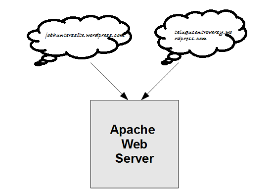
IP-based:
When IP-based virtual hosting is used, each site (either a DNS host name or a group of DNS host names that act the same) points to a unique IP address. The webserver is configured with multiple physical network interfaces, virtual network interfaces on the same physical interface or multiple IP addresses on one interface. The web server can either open separate listening sockets for each IP address, or it can listen on all interfaces with a single socket and obtain the IP address the TCP connection was received on after accepting the connections. Either way, it can use the IP address to determine which website to serve. The client is not involved in this process and therefore (unlike with name-based virtual hosting) there are no compatibility issues.
The downside of this approach is the server needs a different IP address for every web site. This increases administrative overhead (both assigning addresses to servers and justifying the use of those addresses to internet registries) and contributes to IPv4 address exhaustion.
<VirtualHost 192.168.1.1:80>
    ServerName www.example1.com
    DocumentRoot /var/www/example1
</VirtualHost>

<VirtualHost 192.168.1.2:80>
    ServerName www.example2.com
    DocumentRoot /var/www/example2
</VirtualHost>
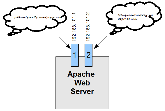
Server side design principles for scalable internet systems
Relatively few design principles are required to design scalable systems. The list is limited to:
-
divide and conquer: small subsystems, each carrying out some well-focused function
-
asynchrony: work can be carried out in the system on a resource available basis
-
encapsulation: loosely coupled components
-
concurrency: activities split across hardware, threads
-
parsimony: each line of code and each piece of state information has a cost
Security and Stuffs
Web-security: TLS, see Security Email security: PGP Communication security: see Security
Firewalls
In addition to the danger of information leaking out, there is also a danger of information leaking in. In particular, viruses, worms, and other digital pests can breach security, destroy valuable data, and waste large amounts of administrators’ time trying to clean up the mess they leave. Often they are imported by careless employees who want to play some nifty new game.
A firewall is a combination of hardware and software that isolates an organization’s internal network from the Internet at large, allowing some packets to pass and blocking others. A firewall allows a network admin to control access between the outside world and resources within the administered network by managing the traffic flow to and from these resources.
Traditional packet filters:
An organization has a gateway router connecting its internal network to its ISP (and hence to the large public Internet). All traffic leaving and entering the internal network passes through this router, and it is at this router where packet filtering occurs. A packet filter examines each datagram in isolation determining whether the datagram should be allowed to pass or should be dropped based on administrator-specific rules. Filtering decisions are typically based on:
- IP source or destination address
- Protocol type in IP datagram filed: TCP, UDP, ICMP, OSPF, and so on
- TCP or UDP source and destination port
- TCP flag bits
- ICMP message type
For example, if the organization doesn’t want any incoming TCP connections except those for its public Web server, it can block all incoming TCP SYN segments except TCP SYN segments with destination port 80 and the destination IP address corresponding to the Web server. If the organization doesn’t want its users to monopolize access bandwidth with Internet radio applications, it can block all not-critical UDP traffic (since Internet radio is often sent over UDP). If the organization doesn’t want its internal network to be mapped (tracerouted) by an outsider, it can block all ICMP TTL expired messages leaving the organization’s network.
Stateful packet filters:
In a traditional packet filter, filtering decisions are made on each packet in isolation. Stateful filters actually track TCP connections, and use this knowledge to make filtering decisions. (old table could be used for ddos). Stateful filters track all ongoing TCP connections in a connection table. This is possible because the firewall can observe the beginning of a new connection by observing a three-way handshake (SYN, SYNACK, and ACK); and it can observe the end of a connection when it sees a FIN packet for the connection.
Application gateway:
To have finer-level security, firewalls must combine packet filters with application gateways. Application gateways look beyond the IP/TCP/UDP headers and make policy decisions based on application data. An application gateway is an application-specific server through which all application data (inbound and outbound) must pass. Multiple application gateways can run on the same host, but each gateway is a separate server with its own processes.
DMZ:
The difficulty is that network administrators want security but cannot cut off communication with the outside world. That arrangement would be much simpler and better for security, but there would be no end to user complaints about it. This is where arrangements such as the DMZ (DeMilitarized Zone) come in handy. The DMZ is the part of the company network that lies outside of the security perimeter. Anything goes here. By placing a machine such as a Web server in the DMZ, computers on the Internet can contact it to browse the company Web site. Now the firewall can be configured to block incoming TCP traffic to port 80 so that computers on the Internet cannot use this port to attack computers on the internal network.
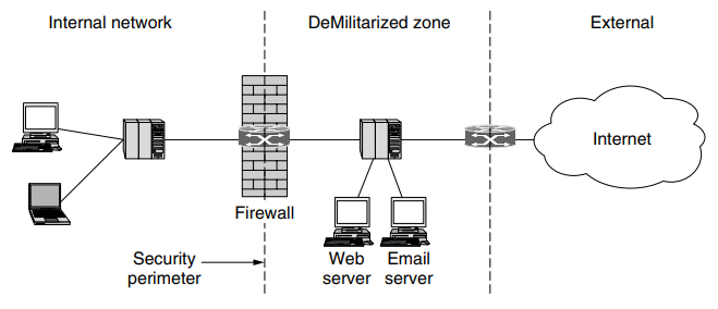
Virtual Private Networks
Many companies have offices and plants scattered over many cities, some-times over multiple countries. In the olden days, before public data networks, it was common for such companies to lease lines from the telephone company between some or all pairs of locations. Some companies still do this. A network built up from company computers and leased telephone lines is called a private network.
Private networks work fine and are very secure. If the only lines available are the leased lines, no traffic can leak out of company locations and intruders have to physically wiretap the lines to break in, which is not easy to do. The problem with private networks is that leasing a dedicated T1 line between two points costs thousands of dollars a month, and T3 lines are many times more expensive. When public data networks and later the Internet appeared, many companies wanted to move their data (and possibly voice) traffic to the public network, but without giving up the security of the private network.
This demand soon led to the invention of VPNs (Virtual Private Networks), which are overlay networks on top of public networks but with most of the properties of private networks. The flexibility is much greater then is provided with leased lines, yet from the perspective of the computers on the VPN, the topology looks just like the private network case.
VPN utilize encryption and other security mechanisms to ensure that only authorized users can access the network and that data cannot be intercepted by outsiders. A VPN can use various protocols (such as OpenVPN, IPSec, or L2TP) to establish and manage the secure connection.
Tunneling
Tunneling is a method by which data packets are encapsulated within other data packets, allowing them to be transmitted across a network using protocols different from those used by the network itself. This tunnel can be used to transport any type of network traffic over any other type of network.
A tunneling protocol, such as GRE (Generic Routing Encapsulation) or IPsec (Internet Protocol Security), encapsulates the data packets to be sent, transmits them across the network, and then de-encapsulates them at the receiving end. Tunneling can include encryption, but it is not mandatory.
Tunneling is used in various scenarios, including VPNs (to secure traffic over the internet), to carry IPv6 traffic over IPv4 networks, and to connect two intranets together over the internet without exposing their traffic to external networks.
IPSec VPN
Confidentiality: Before getting into the specifics of IPsec, let’s step back and consider what it means to provide confidentiality at the network layer. With network-layer confidentiality between a pair of network entities (for example, between two routers, between two hosts, or between a router and a host), the sending entity encrypts the payloads of all the datagrams it sends to the receiving entity. The encrypted payload could be a TCP segment, a UDP segment, an ICMP message, and so on. If such a network-layer service were in place, all data sent from one entity to the other—including e-mail, Web pages, TCP handshake messages, and management messages (such as ICMP and SNMP)—would be hidden from any third party that might be sniffing the network. For this reason, network-layer security is said to provide “blanket coverage.”
Authentication: In addition to confidentiality, a network-layer security protocol could potentially provide other security services. For example, it could provide source authentication, so that the receiving entity can verify the source of the secured datagram. A network-layer security protocol could provide data integrity, so that the receiving entity can check for any tampering of the datagram that may have occurred while the datagram was in transit. A network-layer security service could also provide replay-attack prevention, meaning that Bob could detect any duplicate datagrams that an attacker might insert
IPSec is a secure network protocol suite that authenticates and encrypts packets of data to provide secure encrypted communication between two computers over an IP network.
To get a feel for how a VPN works. When a host in headquarters sends an IP datagram to a salesperson in a hotel, the gateway router in headquuaters converts the vanilla IPv4 datagram into an IPsec datagram and then forwards this IPsec datagram into the internet. The payload of the IPsec datagram includes an IPsec header, which is used for IPsec processing; furthermore, the payload of the IPsec datagram is encrypted. When the IPsec datagram arrives at the salesperson’s laptop, the OS in the laptop decrypts the payload (and provides other security services, such as verifying data integrity) and passes the unencrypted payload to the upper-layer protocol (for example, to TCP or UDP).
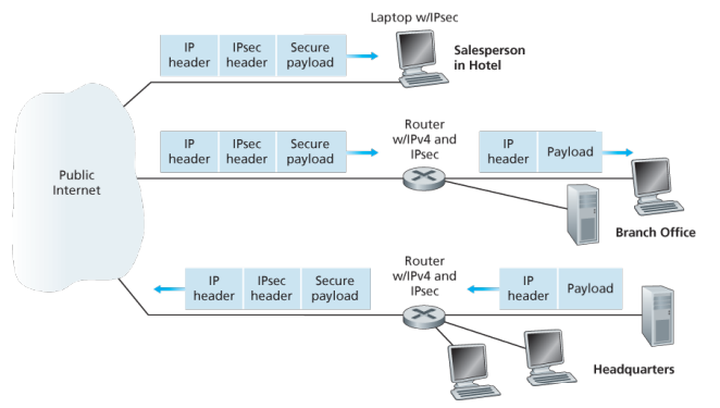
In IPsec protocol suite, there are two principal protocols:
- the Authentication Header (AH) protocol
- Encapsulation Security Payload (ESP) protocol.
When a source IPsec entity (typically a host or a router) sends secure datagrams to a destination entity (also a host or a router), it does so with either the AH protocol or the ESP protocol. The AH protocol provides source authentication and data integrity but does not provide confidentiality. The ESP protocol provides source authentication, data integrity, and confidentiality. Because confidentiality is often critical for VPNs and other IPsec applications, the ESP protocol is much more widely used than the AH protocol.
To a router within the Internet, a packet traveling along a VPN tunnel is just an ordinary packet. The only thing unusual about it is the presence of the IPsec header after the IP header, but since these extra headers have no effect on the forwarding process, the routers do not care about this extra header.
IPsec datagrams are sent between pairs of network entities, such as between two hosts, between two routers, or between a host and router. Before sending IPsec datagrams from source entity to destination entity, the source and destination entities create a network-layer logical connection. This logical connection is called a security association (SA).
What is a SA?
An SA is a simplex logical connection; that is, it is unidirectional from source to destination. If both entities want to send secure datagrams to each other, then two SAs (that is, two logical connections) need to be established, one in each direction
When the system is brought up, each pair of firewalls has to negotiate the parameters of its SA, including the services, modes, algorithms, and keys. If IPsec is used for the tunneling, it is possible to aggregate all traffic between any two pairs of offices onto a single authenticated, encrypted SA, thus providing integrity control, secrecy, and even considerable immunity to traffic analysis.
This institution consists of a headquarters office, a branch office and, say, n traveling salespersons. There are 2+2n SAs.
The IPSec Datagram:
IPSec has two different packet forms, one for the so-called tunnel model and the other for the so-called transport mode. The tunnel model, being more appropriate for VPNs, is more widely deployed than the transport mode. In order to further de-mystify IPsec and avoid much of its complication, we henceforth focus exclusively on the tunnel mode. Once you have a solid grip on the tunnel mode, you should be able to easily learn about the transport mode on your own.
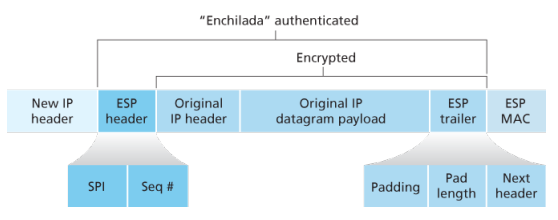
L2TP:
L2TP is a tunneling protocol used to support various private networks (VPNs) or as part of the delivery of services by ISPs. IT uses encryption only for its own control messages (using an optional pre=shared secret), and does not provide any encryption or confidentiality of content by itself. .
The entire L2TP packet, including payload and L2TP header, is sent within an UDP diagram. It is common to carry PPP sessions within an L2TP tunnel. L2Tp does not provide confidentiality or strong authentication by itself. IPSec is often used to secure L2TP packets by providing confidentiality, authentication and integrity. The combination of these two protocols is generally known as L2TP/IPsec.
The two endpoints of an L2TP tunnel are called L2TP access concentrator (LAC) and the L2TP network server (LNS). THe LNS waits for new tunnels. Once a tunnel is established, the network traffic between the peers is bidirectional. To be useful for networking, higher-level protocols are then run through the L2TP tunnel. To facilitate this, an L2TP session is established within the tunnel for each higher-level protocol such as PPP.
Generic Routing Encapsulation (GRE):
GRE is a tunneling protocol developed by Cisco systems that can encapsulate a wide variety of network layers protocols inside virual PPP links or point-to-multipoint links over an Internet Protocol network.
Intranet
An intranet is a computer network for sharing information, easier communication, collaboration tools, operational systems, and other computing services within an organization, usually to the exclusion of access by outsiders. The term is used in contrast to public networks, such as the Internet, but uses the same technology based on the Internet protocol suite.
An organization-wide intranet can constitute an important focal point of internal communication and collaboration, and provide a single starting point to access internet and external resources. In its simplest form, an intranet is established with technologies for LANs and WANs.
An intranet is sometimes contrasted to an extranet. While an intranet is generally restricted to employees of the organization, extranets may also be accessed by customers, suppliers, or other approved parties. Extranets extend a private network onto the Internet with special provisions for authentication, authorization and accounting (AAA protocol).
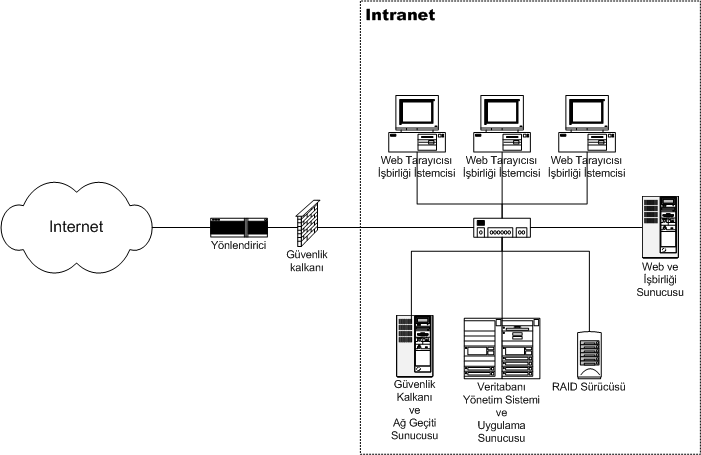
Benefits:
- Workforce productivity: help users to locate and view information faster and use applications relevant to their roles and responsibilities. With the help of a web browser interface, users can access data held in any database the organization wants to make available, anytime.
- Time: allow organizations to distribute information to employees on an as-needed basis. Employees may link to relevant information at their convenience, rather than being distracted indiscriminately by email.
- Communication: serve as powerful tools for communication within an organization, vertically strategic initiatives that have a global reach throughout the organization. By providing this information on the intranet, staff have the opportunity to keep up-to-date with the strategic focus of the organization.
- Web publishing: allows cumbersome corporate knowledge to be maintained and easily accessed through the company using hypermedia and Web technologies.
- Cost savings: reduce costs associated with printing, publishing, and overall maintenance of physical documents.
- Improve teamwork: provides all authorized with access to relevant information and resources, regardless of their location within the organizations
Extranet:
An extranet is a controlled private network that allows access to partners, vendors, and suppliers or an authorized set of customers - normally to a subset of the information from an organization’s intranet. An extranet is similar to a DMZ in that it provides access to needed services for authorized parties, without granting access to an organization’s entire network.
Advantages:
- Exchange large volumes of data using EDI
- Share product catalogs exclusively with trade partners
- Collaborate with other companies on joint development efforts
- Jointly develop and use training programs with other companies
- Provide or access services provided by one company to a group of other companies, such as an online banking application managed by one company on behalf of affiliated banks
- improved efficiency: since the customers are satisfied with the information provided it can be an advantage for the organization where they will get more customers which increases the efficiency.
Disadvantages:
- Extranets can be expensive to implement and maintain within an organization (e.g., hardware, software, employee training costs), if hosted internally rather than by a application service provider.
- Security of extranets can be a concern when hosting valuable or proprietary information.
- Partner and customer access may result in contentious or controversial debates
Content Management
is a very broad filed which comprises many possible implementation scenarios, each with its own requirements and considerations. Content server can manage content-centric website. These can either be published on an intranet, extranet, or the Internet. A content server has a wide variety of content management applications, varying from pure document management on one end of the spectrum to pure web content management on the other. In practice, however, applications are typically somewhere in between, with both document and web content management characteristics.
- B2E (Intranet), B2B(Extranet), B2C (internet) applications
Web content management:
Traditionally, content is published by a webmaster whose main responsibility is the technology, not the content of the site. This may create a serious bottleneck the publishing process, as all contents needs to pass the same point before being put on line. A web content management solution puts content publishing in hands of the content experts, and enables webmasters to focus on their core tasks. This is accomplished by offering tools that automate the publishing process and providing business users with the ability to create web content from their own workplaces. Web content management applications put business users in control of creation, contribution, and updates of content published to a website. This enables non technical users to create material with desktop applications, such as Word and post it to the website with little effort.
WordPress is the most popular web CMS. It was developed as a blogging CMS, but has been adapted into a full fledged CMS. It is generally considered to be the most user-friendly platform and is also the easiest to learn and use. Joomla is a popular web content management system for publishing web content. It is a free and open-source that can be used to easily create and edit web pages. Drupal is also a free and open-source web content management system. It is being used worldwide for various websites ranging from personal blogs to corporate, political and government websites. These web content management systems facilitate collaborative creation of content. They make web publishing fast, easy and affordable.
Collaborative content development system:
Wikis and blogs have emerged as widely accepted environments for collaborative content development. Wiki is a web application that allows users to create and edit content in collaboration with others. Here, the content is developed by a number of users and is moderated by moderator if needed. Blogs are online journals which provide a collaborative space for content in the form of text, graphics, audio or video. Blogs can be easily hyper-linked thus creating large online communities. These applications provide tremendous opportunity for information sharing and ease of collaboration and are characterized by ease of use. Many free open source versions of these tools are available and this has led to their explosive growth. Wiki has been discussed in detail in following section.
Intranet Design Principles
(lets go man)
Roadmap:
The success roadmap for developing a corporate Intranet involves a comprehensive strategy broken down into several key sections. Each section plays a crucial role in ensuring the intranet’s effective planning, development, and implementation.
- Establishing Guidelines
- Define the business case, publishing policies, roles, security, technology standards, content guidelines, and metrics for success.
- Establish guidelines around content ownership, publishing, review processes, allowed technologies, maintenance, etc.
- Create a style guide for consistent look and feel across the intranet.
- Set up a site hierarchy and navigation structure.
- Establish Platform and Infrastructure
- Select a standard browser and rollout plan.
- Implement security measures like user authentication, access control, data encryption.
- Choose a content management system.
- Select HTML authoring tools for technical and non-technical users.
- Decide on database integration standards.
- Implement web analytics tools to track usage.
- Estimate server and bandwidth needs.
- Invite All to Participate
- Promote intranet awareness through events, advertising, training, demos.
- Identify intranet champions to drive adoption.
- Form a steering committee with diverse representation.
- Intranet Team
- Build a dedicated intranet team with roles like webmasters, developers, designers, support.
- Develop a clear support system for end-users and publishers.
Design considerations:
-
Budget: how much can be allocated for the network infrastructure, equipment, software, personnel, etc.
-
Nature of applications: types of apps that will run on the network (e.g. basic office apps, bandwidth intensive apps, real time apps etc.)
-
Fault tolerance: requirements around network, system and application resilience and upline
-
Availability of expertise: whether in-house expertise exists for different technologies or if external consultants need to be engaged.
-
Ease of configuration: how complex the network design and configuration should be based on in-house skills.
-
Management: requirements around monitoring, maintenance, updates
Some equipment that could be necessary:
| Component | Description |
|---|---|
| PCs | End-user computing devices, including desktops and laptops, used for accessing the intranet and internet, running applications, and storing data. |
| Servers | High-performance computers that provide services to other computers on the network. |
| UPS | Backup power units that provide power during outages, ensuring network equipment remains operational. |
| Switches | Network switches that connect devices on a LAN. They can be managed or unmanaged and come in various port densities (e.g., 8, 24, 48 ports). |
| Patch Panels | A panel of ports that consolidate and organize cable connections. Patch cables connect these panels to switches or other equipment. |
| Routers | Devices that route data between different networks, including the intranet and the internet, using IP addresses. They can also perform other functions like firewall. |
| Wireless AP | Devices that allow wireless devices to connect to the network. They extend the network’s reach to areas where cabling isn’t feasible. |
| Twister-Pair | Cables used for carrying signals; includes CAT5e, CAT6, CAT6a, CAT7, CAT8, each supporting different speeds and bandwidths. |
| Fiber Optic | Used for high-speed data transmission over longer distances without electromagnetic interference; includes single-mode and multi-mode fibers. |
| Patch Cables | Short cables used for connecting patch panels to switches or devices to outlets. Typically CAT5e, CAT6, etc., for twisted-pair networks or optical cables for fiber. |
| Firewalls | Hardware or software-based security devices that control incoming and outgoing network traffic based on an organization’s security policies. |
| Rack Cabinets | Stands or cabinets that house network equipment, servers, and patch panels in a standardized frame or enclosure. |
| Faceplates | Plates that mount on a wall or desk, providing a tidy interface for cable connections. They typically house network outlets where patch cables from devices can be connected. |
Small network design
Requirements:
- Less than 80 users
- Low budget for IT expenses
- Little expertise in various technologies
- Mostly off-the-shelf applications with low bandwidth needs
- Basic requirements like email, word processing, printing, file sharing
- One or two admins managing the entire network
Design choices:
Network equipment:
- Low-cost equipment
- Central switch as backbone
- Shared bandwidth for most users
- Switched ports for selected users requiring higher bandwidth
Network topology:
- Flat network design
User connectivity:
- Two user groups - power users and non-power users
- Power users get higher bandwidth for large file transfers while non-power users get lower bandwidth for basic tasks
Addressing:
- Use private IPv4 Class C range (192.168.1.0/24)
- Static IP assignment instead of DHCP
- No internal DNS server, use ISP provided DNS if needed
- Router with NAT functionality
- Outsource email and web services to ISPs
Physical network design:
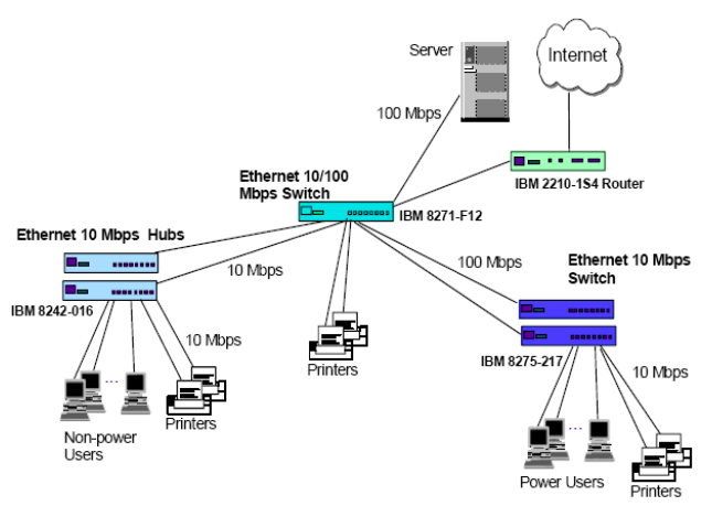
Logical network design:
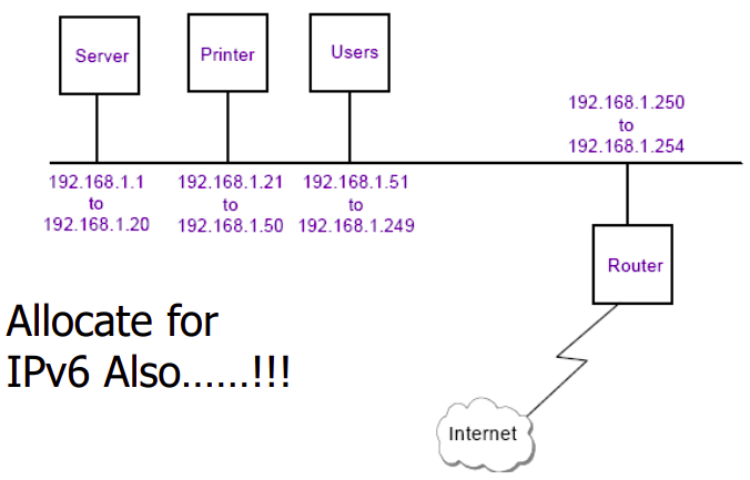
Med network design
Requirements:
- Less than 500 users
- Fixed annual IT budget
- Develop in-house applications
- Run commercial off-the-shelf applications
- Provide dial-in access for mobile workers
- Implement fault tolerance for servers/hosts
Design choices:
Network Equipment:
- Backbone switches
- Access switches (100Mbps and 10Mbps)
- Routers with dial-in/dial-back capabilities
- Firewall
Network Topology:
- Switched network design
User Connectivity:
- 100Mbps switched ports for power users
- 10Mbps switched ports shared 16:1 or 24:1 for other users
- Connectivity segregated by department needs
Addressing:
- Use public IP addresses for internet-facing servicesr
- Use DHCP server for internal client addressing
- Implement internal DNS server
Physical network design:
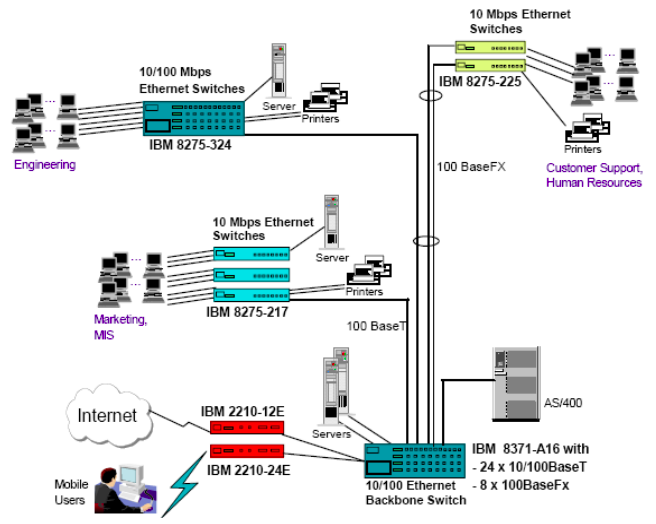
Logical network design:
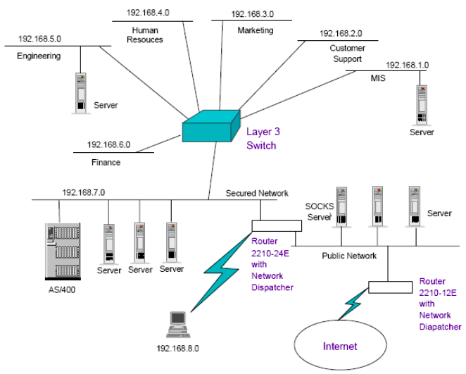
Some shit examples:
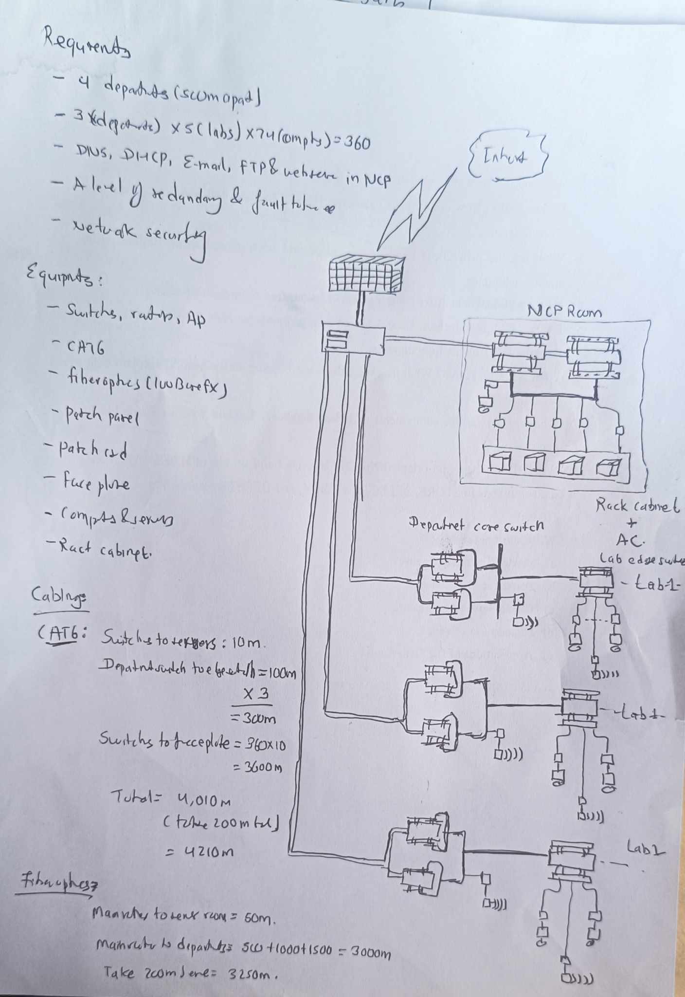
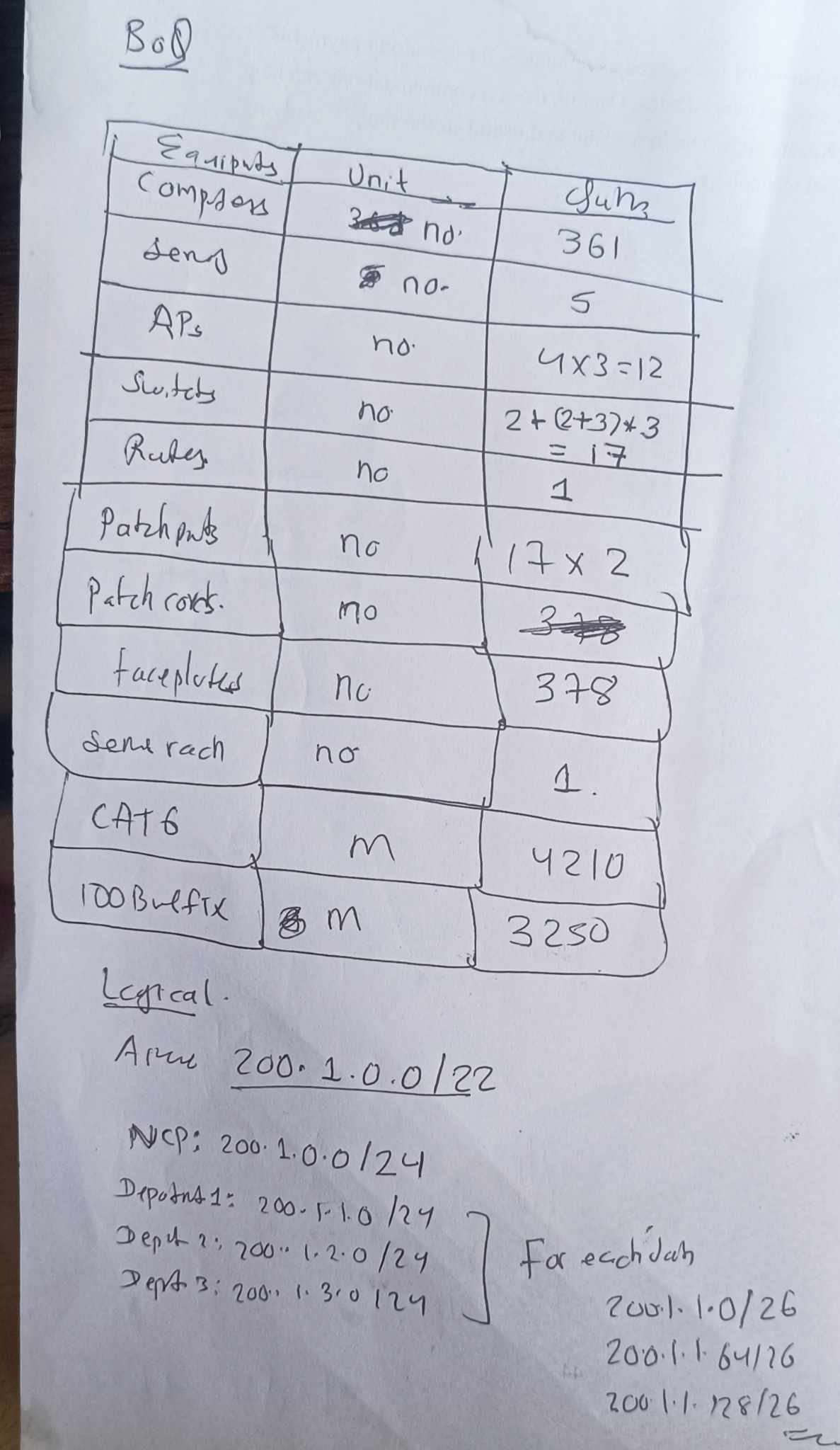
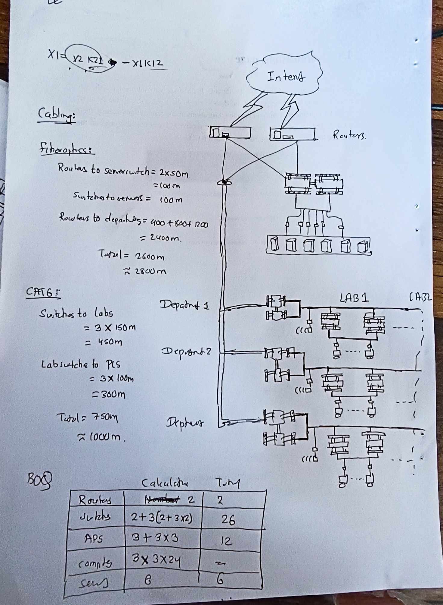
Other Multimedia Applications
Since the Web grew up, however, the Internet has become more about content than communication. Many people use the Web to find information, and there is tremendous amount of peer-to-peer file sharing that is driven by access to movies, music, and programs. The switch to content has been so pronounced that the majority of Internet bandwidth is now used to deliver stored videos.
The taxonomy of multimedia application ca be classified as either:
- streaming stored audio/video
- streaming live audio/video
- conversational voice/video-over-IP
Conversational VOIP
Real-time conversational voice over the Internet is often referred to as Internet telephony, since, from the user’s perspective, it is similar to the traditional circuit-switched telephone service. It is also commonly called Voice-over-IP (VoIP). Conversational video is similar, except that it includes the video of the participants as well as their voices. Most of today’s voice and video conversational systems allow users to create conferences with three or more participants. Conversational voice and video are widely used in the Internet today, with the Internet companies Skype, QQ, and Google Talk boasting hundreds of millions of daily users.
Two of the requirements axes are:
- timing considerations
- tolerance of data class
Timing considerations are important because audio and video conversational applications are highly delay-sensitive. For a conversation with two or more interacting speakers, the delay from when a user speaks or moves until the action is manifested at the other end should be less than a few hundred milliseconds. For voice, delays smaller than 150 milliseconds are not perceived by a human listener, delays between 150 and 400 milliseconds can be acceptable, and delays exceeding 400 milliseconds can result in frustrating, if not completely unintelligible, voice conversations.
Old way (IP protocol) limitations:
-
End to end delay: Accumulates from transmission, processing, and queuing delays. Delays under 150ms are ideal for VoIP; 150-400ms can be acceptable; delays over 400ms degrade conversation quality. Packets arriving after 400ms are discarded.
-
Jitter: Variation in packet arrival times caused by fluctuating queue delay in routers. Jitter can lead to uneven packet spacing, affecting the quality of VoIP calls. Employing timestamps and a playout delay at the receiver can mitigate jitter. Strategies include fixed and adaptive playout delays to balance between minimizing delay and avoiding packet loss.
-
Packet loss: Can occur when network buffers overflow, leading to discarded packets. VoIP typically uses UDP to avoid higher delays associated with TCP’s reliable delivery. Packet loss rates of 1-20% are tolerable, with FEC helping to recover lost data.
Protocols:
Real-time conversational applications, including VoIP and video conferencing, are compelling and very popular. It is therefore not surprising that standards bodies, such as the IETF and ITU, have been busy for many years (and continue to be busy!) at hammering out standards for this class of applications.
VoIP has been implemented with proprietary protocols and protocols based on open standards in applications such as VoIP phones, web applications, and web based communications.
VoIP protocols include:
- Session initiation protocol (SIP), connection management protocol developed by IETF
- Real time transport protocol (RTP), transport protocol for real-time audio and video data
- Skype protocol, proprietary Internet telephony protocol suite based on peer-to-peer architecture
RTP basics:
The sender side of a VoIP application appends header fields to the audio chunks before passing them to the transport layer. These header files include sequence number and timestamps. Since most multimedia networking applications can make use of sequence numbers and timestamps, it is convenient to have a standardized packet structure that includes fields for audio/video data, sequence number, and timestamp, as well as other potentially useful fields. RTP is such a standard.
RTP typically runs on top of UDP. The sending side encapsulates a media chunk within an RTP packet, then encapsulates the packet in a UDP segment, and then hands the segment to IP. The receiving side extracts the RTP packet from the UDP segment, then extracts the media chunk from the RTP packet, and then passes the chunk to the media player for decoding and rendering.
As an example, consider the use of RTP to transport voice. Suppose the voice source is PCM-encoded (that is, sampled, quantized, and digitized) at 64 kbps. Further suppose that the application collects the encoded data in 20-msec chunks, that is, 160 bytes in a chunk. The sending side precedes each chunk of the audio data with an RTP header that includes the type of audio encoding, a sequence number, and a timestamp. The RTP header is normally 12 bytes. The audio chunk along with the RTP header form the RTP packet. The RTP packet is then sent into the UDP socket interface. At the receiver side, the application receives the RTP packet from its socket interface. The application extracts the audio chunk from the RTP packet and uses the header fields of the RTP packet to properly decode and play back the audio chunk.
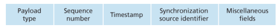
SIP basics:
The SIP is an open and lightweight protocol that does the following:
- It provides mechanisms for establishing calls between a caller and a callee over an IP network. It allows the caller to notify the callee that it wants to start a call. It allows the participants to agree on media encodings. It also allows participants to end calls.
- It provides mechanisms for call management, such as adding new media streams during the call, changing the encoding during the call, inviting new participants during the call, call transfer, and call holding
- It provides mechanisms for the caller to determine the current IP address of the callee. Users do not have a single, fixed IP address because they may be assigned addresses dynamically (using DHCP) and because they may have multiple IP devices, each with a different IP address.
Video streaming:
From a networking perspective, the most salient characteristic of video is its high bit rate, ranges from 100 kbps or low-quality video to over 3 Mbps for streaming high-definition movies; 4K streaming envisions a bitrate of more than 10Mbps. Another important characteristic of video is that it can be compressed, thereby trading off video quality with bit rate. A video is a sequence of images, typically being displayed at a constant rate, for example, at 24 or 30 images per second. An uncompressed, digitally encoded image consists of an array of pixels, with each pixel encoded into a number of bits to represent luminance and color.
Old way (there is also UDP way):
- In HTTP streaming, the video is simply stored at an HTTP server as an ordinary file with a specific URL, when a user wants to see the video, the client establishes a TCP connection with the server and issues an HTTP GET request.
- On the client side, the bytes are collected in a client application buffer, once the number of bytes in this buffer exceeds a predetermined threshold, the client application begins playback, the streaming video application periodically grabs video games from the client application buffer, decompresses and displays on the screen.
- Major shortcoming is that all clients receive the same encoding of the video, despite the large variations in the amount of bandwidth available to a client, both across different clients and also over time for the same client.
DASH way:
In Dynamic Adaptive Streaming over HTTP, the video is encoded into several different versions, with each version having a different bit rate, and correspondingly, a different quality. The client dynamically requests chunks of video segments of a few seconds in length, when the amount of available bandwidth is high, the client naturally selects chunks from a high-rate version; and when the available bandwidth is low, it naturally selects from a low-rate version.
Content distribution networks:
The most straightforward approach to provide video streaming is to build massive data center, store all of the videos in it and stream videos directly from the data center to clients worldwide.
Three major problems with this approach:
- If the client is far from data center, server-to-client packets will cross many communication links and likely pass through many ISPs, with some of the ISPs possibly located on different continents, if one of these links provides a throughput that is less than the video consumption rate, the end-to-end throughput will also be below consumption rate, resulting in freezing.
- Popular video will likely be sent many times over the same communication links, not only wastes bandwidth, but video company will be paying its provider ISP for sending the same bytes into the Internet over and over again
- Data center as a single point of failure
Almost all video-streaming companies make use of CDNs, that manages servers in multiple geographically distributed locations, stores copies of the videos and other types of Web content, including documents, images and audio in its severs and attempts to direct each user request to a CDN location that will provide the best user experience.
The CDN may be a private CDN, that is, owned by the content provider itself; for example, Google’s CDN distributes Youtube videos and other types of content.
CDNs typically adopt one of two different server placement philosophies:
- Enter deep, into the access networks of ISP, by deploying server clusters in access ISPs all over the world. The goal is to get close to end users, thereby improving user-perceived deploy and throughput by decreasing the number of links and routers between the end user and the CDN server from which it receives content. Akamai takes this approach with clusters in approximately 1,700 locations.
- Bring home, instead of getting inside the access ISPs, these CDNs typically place their clusters in IXPs. Compared with the enter-deep design philosophy, the bring-home design typically results in lower maintenance and management overhead, possibly at the expense of higher delay and lower throughput to end users
Once its clusters are in place, the CDN replicates content across its clusters, may not want to place a copy of every video in each cluster, since some videos are rarely viewed or are only popular in some countries. Many CDNs do not push videos to their clusters but instead use a simple pull strategy; if a client requests a video from a cluster that is not storing the video, then the cluster retrieves the video from the central or from another cluster and stores a copy locally while streaming the video to the client at the same time
CDN Operation:
When browser requests a video, the CDN must intercept the request so that
- it can determine a suitable CDN server cluster for that client at that time,
- and redirect the client’s request to a server in that cluster.
Most CDNs take advantage of DNS to intercept and redirect requests. Let’s consider a simple example to illustrate how the DNS is typically involved. Suppose a content provider, NetCinema, employs the third-party CDN company, KingCDN, to distribute its videos to its customers
- The user visits the Web page at NetCinema
- When the user clicks on the link, the user’s host sends a DNS query for
video.netcinema.com - The user’s Local DNS server relays the query to an authoritative DNS server for NetCinema which observes the string video in the hostsname
- Hands over the DNS query to KingCDN instead of returning an IP address, the NetCinema authoritative DNS server returns to the LDNS a hostname in KingCDN’s domain for example,
a1105.kingcdn.com - From this point on, the DNS query enters into KingCDN’s private DNS infrastrucutre, the user’s LDNS then sends a second query now for
a1003.kingcdn.com, and KingCDN’s DNS eventually returns the IP address of a KingCDN content server to the LDNS - The LDNS forwards the IP address of the conente-serving CND node to ithe user’s host
- Once the client receives the IP address for a KingCDN content server, it establishes direct TCP connection
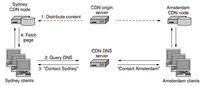
At the core of any CDN deployment is a cluster selection strategy, that is, mechanism for dynamically directing clients to a server cluster or a data center within the CDN. As we just saw, the CDN learns the IP address of the client’s LDNS server via the client’s DNS lookup. After learning this IP address, the CDN needs to select an appropriate cluster based on this IP address. CDNs generally employ proprietary cluster selection strategies. We now briefly survey a few approaches, each of which has its own advantages and disadvantages. One simple strategy is to assign the client to the cluster that is geographically closest.
IP Interconnection
Interconnection refers to the practice of linking the networks of multiple service providers, allowing their users to interact or communicate. This can be a physical connection, like those made through E1 or T1 lines, or a virtual one, such as IP-to-IP connections. The process encompasses both technical setup and commercial negotiations, aiming to achieve the best possible balance of cost and quality for accessing another provider’s network or the Public Switched Telephone Network (PSTN).
VoIP-PSTN Interconnection:
For VoIP (Voice over Internet Protocol) providers, especially smaller ones looking to terminate calls domestically, interconnection is typically with major national operators or tier 1 providers like AT&T, BT, etc. These interconnections are often facilitated through E1/T1 lines, enabling the simultaneous transmission of multiple voice or data channels. However, this method presents challenges for small VoIP businesses primarily using IP-based softswitches for call management due to the need for additional equipment (VoIP-PSTN gateways or BRI/PRI cards), making it expensive and complex. Moreover, the peering process can be intricate, often with high minimum traffic requirements that may not be feasible for smaller operators.
IP-to-IP (VoIP) Interconnection:
IP-to-IP interconnection is a simpler and more cost-effective option for VoIP startups. This method requires just a VoIP softswitch, with no need for extra hardware. Setting up is straightforward, and many wholesale providers can be found through directories like Voip Providers List and voip-info.org. These wholesalers typically inquire about the traffic volume, type, and top destinations during initial negotiations. Starting termination calls usually just requires a minimal prepaid amount, making it accessible even for small volumes of traffic.
Interconnection Agreement:
After the technical and commercial discussions, an interconnection agreement is signed, outlining the terms under which the networks will connect and exchange traffic. This agreement covers aspects like settlement rates, payment schemes, routing policies, and technical standards, among others. Traffic exchange can be one-way, where one provider is the originator and the other the terminator, or bilateral, where both providers exchange traffic in both directions.
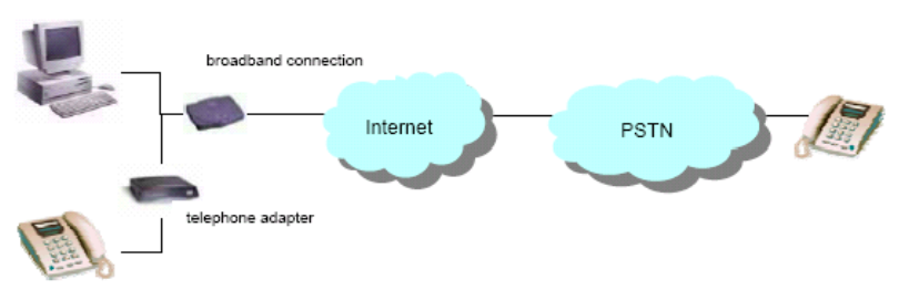
The majority of connections take place according to one of two basic interconnection models:
-
peering: mutual agreement between ISPs to exchange traffic directly between their respective networks. This exchange is typically free, meaning neither party charges the other for the data exchanged. The primary goal is to reduce the distance that data must travel, improve network performance, and decrease latency by avoiding intermediary networks.
-
transit: a service provided by ISPs to carry internet traffic between their customers and the rest of the internet. The transit provider allows traffic to flow to and from its customer networks and all possible destinations on the internet, including networks with which it has peering agreements.
Ecommerce
E-commerce involves conducting business electronically across networks and the internet, encompassing the purchase and sale of goods, services, and information via computer networks. It leverages various technologies like Electronic Data Interchange (EDI), email, intranets, and extranets to process commercial transactions.
E-business is broader form of EC, that also includes:
- Servicing cutsomres
- Collaborating with business partners
- Carry out transactions electronically within transaction.
Benefits:
- For Organizations: Expands market reach, reduces operational costs, enables just-in-time supply chain management, and supports business process reengineering.
- For Consumers: Offers a wider range of products and services, competitive pricing, convenience of shopping anytime and anywhere, and personalized shopping experiences.
- For Society: Reduces traffic congestion and air pollution, raises the standard of living for less affluent individuals, and makes products and services accessible to remote areas.
Limitations:
- Technical Limitations: Include issues like system security, reliability, lack of standards, integration challenges with existing systems, and the need for specialized infrastructure.
- Non-Technical Limitations: Encompass unresolved legal issues, regulatory ambiguities, measurement and justification challenges, resistance to change among consumers, and the need for a critical mass of participants to ensure profitability.
Commerce in Intranet:
- Internal sales: Companies can use their Intranet to sell products or services to their employees, often at discounted rates.
- Inter-department transactions: Intranets enable different departments within a company to buy, sell, or trade services and products among themselves efficiently.
- Information sharing: Product catalogs, order forms, and transaction records can be shared internally, streamlining the purchasing process.
Benefits: cost reduction, increased efficiency, improved communication Disadvantages: Limited scope, security risks, maintenance costs
Commerce in Extranet:
- Collaboration with External Partners: Enables secure interaction and transactions with suppliers, customers, and partners.
- Access to Resources: External parties can access selected parts of a company’s intranet, such as inventory databases or order statuses, facilitating B2B (Business-to-Business) transactions.
- Shared Workspaces: Companies can create shared online spaces for project collaboration with external partners.
Benefits: expanded market reach, enhanced collaboration, cost-effective marketing Disadvantages: complex security needs, management challenges, dependency on technology