Telephone Network
The facilities PSTN were designed many years ago, with a completely different goal in mind: transmitting the human voice many years ago, with a completely different goal: transmitting human voice in more-or-less recognizable form.
The telephone system is tightly intertwined with wide area computer networks. The limiting factor for networking purposes turns out to be the last mile over which customers connect, not the trunks and switches inside the telephone network.
The initial market after Graham Bell, was for the sale of telephones, which came in pairs. It was up to the customer to string a single wire between them. The Bell Telephone Company opened its first switching office which ran a wire to each customer’s house or office. To make a call, the customer would crank the phone to make a ringing sound in the telephone company office to attract the attention of an operator, who would then manually connect the caller to the callee by using a short jumper cable to connect the caller to the callee. Bell System switching offices were springing up everywhere and people wanted to make long-distance calls between cities, so the Bell System began to connect the switching offices.
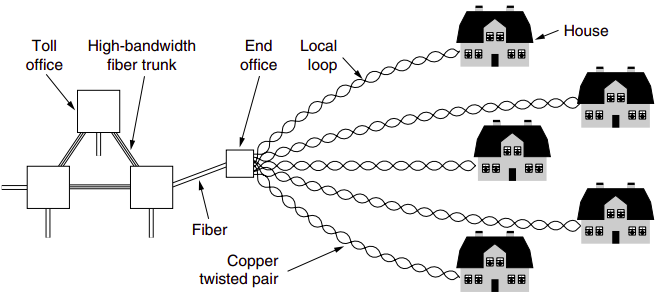
A variety of transmission media are used for telecommunication. Unlike modern office buildings, where the wiring is commonly Category 5, local loops to homes mostly consist of Category 3 twisted pairs, with fiber just starting to appear. Between switching offices, coaxial cables, microwaves, and especially fiber optics are widely used. With the advent of fiber optics, digital electronics, and computers, all the trunks and switches are now digital, leaving the local loop as the last piece of analog technology in the system.
If a subscriber attached to a given end office calls another subscriber attached to the same end office, the switching mechanism within the office sets up a direct electrical connection between the two local loops. This connection remains intact for the duration of the call. If the called telephone is attached to another end office, a different procedure has to be used. Each end office has a number of outgoing lines to one or more nearby switching centers, called toll offices.
Modems
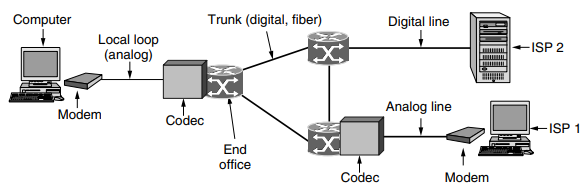
To send bits over the local loop, or any other physical channel for that matter, they must be converted to analog signals that can be transmitted over the channel. This conversion is accomplished using the methods for digital modulation that we studied in the previous section. At the other end of the channel, the analog signal is converted back to bits. device that converts between a stream of digital bits and an analog signal that represents the bits is called a modem, which is short for ‘‘modulator demodulator.’’
Telephone modems are used to send bits between two computers over a voice-grade telephone line, in place of the conversation that usually fills the line. The main difficulty in doing so is that a voice-grade telephone line is limited to 3100 Hz, about what is sufficient to carry a conversation. This bandwidth is more than four orders of magnitude less than the bandwidth that is used for Ethernet.
The Nyquist theorem tells us that even with a perfect 3000-Hz line (which a telephone line is decidedly not), there is no point in sending symbols at a rate faster than 6000 baud. In practice, most modems send at a rate of 2400 symbols/sec, or 2400 baud, and focus on getting multiple bits per symbol while allowing traffic in both directions at the same time.
The humble 2400-bps modem uses 0 volts for a logical 0 and 1 volt for a logical 1, with 1 bit per symbol. One step up, it can use four different symbols, as in the four phases of QPSK, so with 2 bits/symbol it can get a data rate of 4800 bps.
The V.32 modem standard uses 32 constellation points to transmit 4 data bits and 1 check bit per symbol at 2400 baud to achieve 9600 bps with error correction. The final modem in this series is V.34 bis which uses 14 data bits/symbol at 2400 baud to achieve 33,600 bps.
The reason that standard modems stop at 33,600 is that the Shannon limit for the telephone system is about 35 kbps based on the average length of local loops and the quality of these lines. Going faster than this would violate the laws of physics.
(line encoding garera balla digital modulation gardo raixa haina, ani telephone use garda internet nachalni raixa)
Digital Subscriber Line
Their answer was to offer new digital services over the local loop. Initially, there were many overlapping high-speed offerings, all under the general name of xDSL (Digital Subscriber Line), for various x. Services with more bandwidth than standard telephone service are sometimes called broadband.
The reason that modems are so slow is that telephones were invented for carrying the human voice and the entire system has been carefully optimized for this purpose. Data have always been stepchildren. At the point where each local loop terminates in the end office, the wire runs through a filter that attenuates all frequencies below 300 Hz and above 3400 Hz. The cutoff is not sharp—300 Hz and 3400 Hz are the 3-dB points—so the bandwidth is usually quoted as 4000 Hz even though the distance between the 3 dB points is 3100 Hz.
The trick that makes xDSL work is that when a customer subscribes to it, the incoming line is connected to a different kind of switch, one that does not have this filter, thus making the entire capacity of the local loop available. The limiting factor then becomes the physics of the local loop, which supports roughly 1 MHz, not the artificial 3100 Hz bandwidth created by the filter.
The trick that makes xDSL work is that when a customer subscribes to it, the incoming line is connected to a different kind of switch, one that does not have this filter, thus making the entire capacity fo the local loop available. The limiting factor then becomes the physics of the local loop, which supports roughly 1 MHz, not the artificial 3100 Hz bandwidth created by the filter.
Unfortunately, the capacity of the local loop falls rather quickly with distance from the end office as the signal is increasingly degraded along the wire. It also depends on the thickness and general quality of the twisted pair.
The xDSL services have all been designed with certain goals in mind. First, the services must work over the existing Category 3 twisted pair local loops. Second, they must not affect customers’ existing telephones and fax machines. Third, they must be much faster than 56 kbps. Fourth, they should be always on, with just a monthly charge and no per-minute charge.
To meet the technical goals, the available 1.1 MHz spectrum on the local loop is divided into 256 independent channels of 4312.5 Hz each. The OFDM scheme, which we saw in the previous section, is used to send data over these channels, though it is often called DMT (Discrete MultiTone) in the context of ADSL.
Channel 0 is used for POTS (Plain Old Telephone Service). Channels 1–5 are not used, to keep the voice and data signals from interfering with each other. Of the remaining 250 channels, one is used for upstream control and one is used for downstream control. The rest are available for user data.
It is up to the provider to determine how many channels are used for upstream and how many for downstream. A 50/50 mix of upstream and downstream is technically possible, but most providers allocate something like 80–90% of the bandwidth to the downstream channel since most users download more data than they upload. A common split is 32 channels for upstream and the rest downstream.
The international ADSL standard, known as G.dmt, was approved in 1999. It allows speeds of as much as 8 Mbps downstream and 1 Mbps upstream. It was superseded by a second generation in 2002, called ADSL2, with various improvements to allow speeds of as much as 12 Mbps downstream and 1 Mbps upstream. Now we have ADSL2+, which doubles the downstream speed to 24 Mbps by doubling the bandwidth to use 2.2 MHz over the twisted pair.
Within each channel, QAM modulation is used at a rate of roughly 4000 symbols/sec. Different channels may have different data rates, with up to 15 bits per symbol sent on a channel with a high SNR, and down to 2, 1, or no bits per symbol sent on a channel with a low SNR depending on the standard.
In this scheme, a telephone company technician must install a NID (Network Interface Device) on the customer’s premises. This small plastic box marks the end of the telephone company’s property and the start of the customer’s property. Close to the NID (or sometimes combined with it) is a splitter, an analog filter that separates the 0–4000-Hz band used by POTS from the data. The POTS signal is routed to the existing telephone or fax machine. The data signal is routed to an ADSL modem, which uses digital signal processing to implement OFDM.
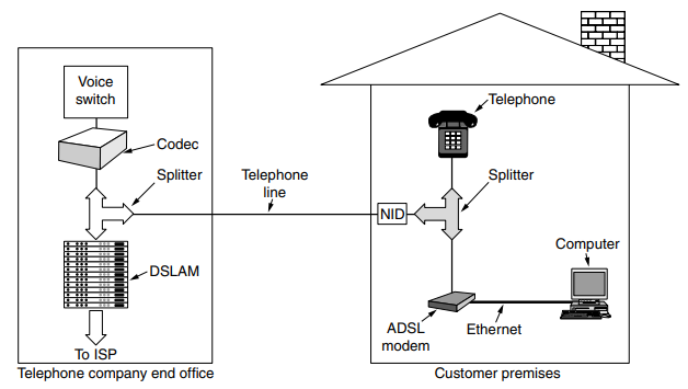
At the other end of the wire, on the end office side, a corresponding splitter is installed. Here, the voice portion of the signal is filtered out and sent to the normal voice switch. The signal above 26 kHz is routed to a new kind of device called a DSLAM (Digital Subscriber Line Access Multiplexer), which contains the same kind of digital signal processor as the ADSL modem. Once the bits have been recovered from the signal, packets are formed and sent off to the ISP.
This complete separation between the voice system and ADSL makes it relatively easy for a telephone company to deploy ADSL. All that is needed is buying a DSLAM and splitter and attaching the ADSL subscribers to the splitter.
Fiber To The Home
Deployed copper local loops limit the performance of ADSL and telephone modems. To let them provide faster and better network services, telephone companies are upgrading local loops at every opportunity by installing optical fiber all the way to houses and offices. The result is called FttH (Fiber To The Home).
Usually, the fibers from the houses are joined together so that only a single fiber reaches the end office per group of up to 100 houses. In the downstream direction, optical splitters divide the signal from the end office so that it reaches all the houses. Encryption is needed for security if only one house should be able to decode the signal. In the upstream direction, optical combiners merge the signals from the houses into a single signal that is received at the end office. This architecture is called a PON (Passive Optical Network).
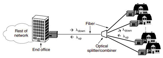
Some protocol is needed to share the capacity of the single fiber at the end office between the different houses. The downstream direction is easy. The end office can send messages to each different house in whatever order it likes. In the upstream direction, however, messages from different houses cannot be sent at the same time, or different signals would collide. The houses also cannot hear each other’s transmissions so they cannot listen before transmitting. The solution is that equipment at the houses requests and is granted time slots to use by equipment in the end office. For this to work, there is a ranging process to adjust the transmission times from the houses so that all the signals received at the end office are synchronized.
Trunks
Trunks in the telephone network are not only much faster than the local loops, they are different in two other respects. The core of the telephone network carries digital information, not analog information; that is, bits not voice. This necessitates a conversion at the end office to digital form for transmission over the longhaul trunks. The trunks carry thousands, even millions, of calls simultaneously. This sharing is important for achieving economies of scale, since it costs essentially the same amount of money to install and maintain a high-bandwidth trunk as a low-bandwidth trunk between two switching offices. It is accomplished with versions of TDM and FDM multiplexing.
Early in the development of the telephone network, the core handled voice calls as analog information. FDM techniques were used for many years to multiplex 4000-Hz voice channels (comprised of 3100 Hz plus guard bands) into larger and larger units. These FDM methods are still used over some copper wires and microwave channels. However, FDM requires analog circuitry and is not amenable to being done by a computer. In contrast, TDM can be handled entirely by digital electronics, so it has become far more widespread in recent years. Since TDM can only be used for digital data and the local loops produce analog signals, a conversion is needed from analog to digital in the end office, where all the individual local loops come together to be combined onto outgoing trunks.
The analog signals are digitized in the end office by a device called a codec. The codec makes 8000 samples per second (125 μsec/sample) because the Nyquist theorem says that this is sufficient to capture all the information from the 4-kHz telephone channel bandwidth. This technique is called PCM (Pulse Code Modulation). It forms the heart of the modern telephone system.
At the other end of the call, an analog signal is recreated from the quantized samples by playing them out (and smoothing them) over time. It will not be exactly the same as the original analog signal, even though we sampled at the Nyquist rate, because the samples were quantized.
TDM based on PCM is used to carry multiple voice calls over trunks by sending a sample from each call every 125 μsec. When digital transmission began emerging as a feasible technology, ITU (then called CCITT) was unable to reach agreement on an international standard for PCM. In the early days of fiber optics, every telephone company had its own proprietary optical TDM system. After AT&T was broken up in 1984, local telephone companies had to connect to multiple long-distance carriers, all with different optical TDM systems, so the need for standardization became obvious. Later, ITU joined the effort, which resulted in a SONET standard and a set of parallel ITU recommendations. The ITU recommendations are called SDH (Synchronous Digital Hierarchy) but differ from SONET only in minor ways.
A form of frequency division multiplexing is used as well as TDM to harness the tremendous bandwidth of fiber optic channels. It is called WDM (Wavelength Division Multiplexing). This way of operating is just frequency division multiplexing at very high frequencies, with the term WDM owing to the description of fiber optic channels by their wavelength or color rather than frequency. The only difference with electrical FDM is that an optical system using a diffraction grating is completely passive and thus highly reliable.
Cable Networks
An antenna on a hill to catch television signals off air, Lay cable between the cities to connect into a single system.
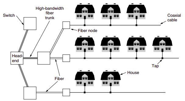
Two-way amplifiers. 54-550MHz region except for FM radio from 88 to 108 MHz, 6 MHz wide channels, QAM-64 modulation, Standard rates up to 42.8 Mbps and upstream rates of up to 30.7 Mbps, CDMA, Shared broadcast medium.
Mobile Networks
Three distinct generations,
2G: GSM as dominant 2G standardization, Frequency division duplex cellular system, A single frequency pair split by time-division multiplexing,
3G: WCDMA,
4G: 4G systems under the name of LTE,
Satellites
Satellite position determined by it’s period and presence of Van Allen belts,
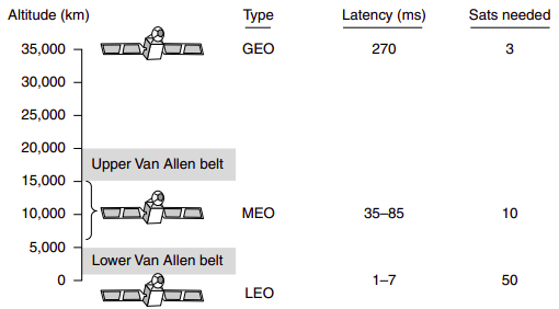
Geostationary Satellites: A satellite at an altitude of 35,000 km in a circular equatorial orbit remains motionless, 40 transponders,
Medium Earth Satellites: For navigation systems rather than telecommunications, Constellation of roughly 30 GPS satellites orbiting at 20,200 km.
Low Earth Satellites: Spying and imaging applications