What does the transport layer do in the layered architecture context? Provides efficient, reliable, and cost-effective data transmission service to its users, normally processes in the application layer.
What does it look like from application and network layer’s perspective? Provides logical communication between application processes running on different hosts as if the hosts running the processes were directly connected, to achieve which, extends the network layer’s delivery service between two end systems to a delivery between two application-layer processes running on the end systems.
Why separate network and transport layer, why not merge them? Runs entirely on the user’s machines, but the network layer runs on the routers, operated by the carriers.
What possesses difficulty to its functioning that it’s worthy to be a separate layer? Two entities need to communicate reliably over a medium with inadequate service that the users have no real control over network layer, and it may lose and corrupt data.
Multiplexing and De-multiplexing
What’s the scenario like when a network layer packet arrives? When the transport layer receives data from the network layer below, needs to redirect the received data to one of the running processes where each process can have one or more sockets, doors through which data passes from the process to the network, thus transport layer in the receiving host actually delivers data to an intermediary socket.
What is a socket again? A network socket is a software structure defined by an application programming interface (API) within a network node that serves as an endpoint for sending and receiving data across the network.
- Provides a low-level programming interface, offering fine-grained control over network communication.
- Multiple processes can run on the same device each with its own set of sockets.
- Supported by multiple programming languages and operating systems, facilitating cross-platform network application development
- Sockets provide the information necessary for firewalls to filter and control network traffic to ensure network security.
So there are many sockets? how to identify them? some addressing, I guess Because at any time there can be more than one socket in the receiving host, each socket has a unique identifier, the format of the identifier depends on whether the socket is UDP or a TCP, where each one is a 16 bit number, ports from 0 to 1023 are well known port numbers and are restricted.
What exactly is a port number? A port number is a number assigned to uniquely identify a connection endpoint and to direct data to a specific service.
How does demultiplexing happen? Each transport layer segment has a set of fields in the segment for this purpose, the transport layer examines the fields to identify the receiving socket and then directs the segment to that socket, called demultiplexing.
How does multiplexing happen? The job is gathering data chunks at the source host from different sockets, encapsulating each data chunk with header to create segments, and passing the segments to the network layer is called multiplexing.
So, in summary, what are the requirements to enable mux and demux? Hence transport layer multiplexing requires
- sockets have unique identifiers
- each segment have special fields that indicate the socket to which the segment is to be delivered
Connection-less UDP
What does UDP fit in this context, I heard it is connection-less? Takes messages from the application process, attaches source and destination port number fields for the multiplexing/demultiplexing service, adds small fields such as length and checksum, passes the resulting segment to the network layer.
Explain me in detail please? Suppose a process in Host A, with UDP port 19157 wants to send a chunk of application data to a process with UDP port 46428 in Host B:
- The transport layer in Host A creates a transport-layer segment that includes the application data, the source port number (19157), the destination port number (46428) and two other values.
- Then passes the resulting segment to the network layer, which encapsulates the segment in an IP datagram and makes a best effort attempt to deliver the segment to the receiving host.
- If the segment arrives at the receiving host B, the transport layer at the receiving host examines the destination port in the segment 46428 and delivers the segment to its socket.
- Note that the host B could be running multiple processes, with its own UDP socket and associated port number. Hence, a UDP socket is fully identified by a two tuple consisting of a destination IP address and a destination port number
Mind explaining the code?
from socket import socket
clientSocket = socket(AF_INET, SOCK_DGRAM)
*Why put source port into the segment? The purpose of source port number serves as a part of return address when B wants to send a segment back to A.
Such a unreliable thing, why even bother using UDP? Some application are better suited for UDP for following reasons
-
Finer application level control over what data is sent and when. As soon as application process passes data to UDP, will package data inside and immediately pass to network layer.
-
No connection establishment. UDP just blasts away without formality while TCP uses a three way handshake.
-
No connection state. TCP maintains a connection state in the end systems, includes receive and send buffers, congestion control parameters, and sequence and acknowledgement number parameters
-
Small packet header overhead: TCP has 20 bytes of header overhead in every segment, whereas UDP has only 8 bytes of overhead.
-
Possible for an application to have reliable data transfer when using UDP, can be done if reliability is built into the application itself.
Okay show me the what a UDP segment look like?
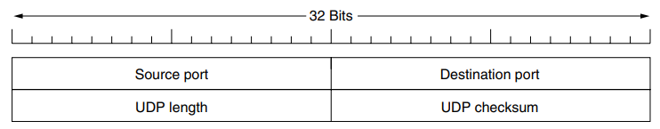
Why need UDP length field? An explicit length value is needed since the size of the data field may differ from one UDP segment to the next, minimum length is 8 bytes, to cover the header and the maximum is 65,515 bytes, which is lower than the largest number that will fit in 16 bits because of the size limit in IP packets.
Why need checksum when it’s already available at data link? (Error Control) Even though many link layer provides error checking, there is no guarantee that all the links between source and destination provide error checking; further if segments are correctly transferred across a link, its possible that bit errors could be introduced when a segment is stored in a router’s memory.
So UDP does error checking? Although UDP provides error checking, does not do anything to recover from an error, some implementations of UDP simply discard the damaged segment; others pass the damaged segment to the application with a warning.
Any particular example concerned with UDP? (Remote Procedure Call)
Connection-oriented TCP
I understood the UDP socket, tell me the differences to the TCP? One subtle difference between a TCP socket and a UDP socket is that a TCP socket is identified by a four-tuple: (source IP, source port, destination IP, destination port), when a TCP segment arrives from the network to a host, the host uses all four values to direct (demultiplex) the segment to the appropriate socket, in contrast with UDP, two arriving TCP segments with different source IP addresses or source port numbers will guaranteed be directed to two different sockets (expect of a TCP segment carrying original connection request)
A bit in detail please, the procedure with an example? like in UDP case.
- The TCP server has a welcoming socket that waits for connection establishment requests from TCP clients on port number 12000.
- The TCP client creates a socket and sends a connection establishment request segment with a special connection establishment bit set in the TCP header.
- When the host OS of the computer running the server process receives the incoming connection request segment with destination port 12000, it locates the server process that is waiting to accept a connection on the port number 12000.
- The server creates a new socket by inheriting the same port number on which it listened.
So simultaneous TCP connections can be established on the same port? Server host may support many simultaneous TCP connection socket, with each socket attached to a process, and with each socket identified by its own four tuple, when a TCP segment arrives at the host, all four fields are used to direct the segment to the appropriate socket.
- Consider a host running a Web server such as Apache on port 80, when clients send segments to the server, all segments will have destination port 80, both initial connection establishment segments and the segments carrying HTTP messages will have 80.
- The server distinguishes the segments from the different clients using source IP addresses and source port numbers.
- Web server spawns a new process for each connection, each of these processe has its own connection socket through which HTTP requests arrive and HTTP responses are sent.
- If the client and server are using persistent HTTP, then throughout the duration of persistent connection the client and server exchange HTTP messages via the same socket, but if client server use non persistent HTTP, then a new TCP connection is created and closed for every request/response, and hence a new socket is created and later closed for every request/response.
- Can impact performance although number of OS tricks can be used to mitigate the problem.
How does TCP ensure reliability? (Principles of Reliable Transfer)
What principles do TCP use in practice? TCP relies on many of the underlying principles including error detection, re-transmissions, cumulative acknowledgements, timers, and header fields for sequence and acknowledgement numbers.
Connection establishment and release
How exactly is the connection we are talking about? The TCP connection is not an end-to-end TDM or FDM circuit as in a circuit-switched network, instead, the connection is a logical one, with common state residing only in TCPs in two communicating end systems, the intermediate network elements do not maintain TCP connection state, in fact, the they are completely oblivious to TCP connections; they use datagrams, not connections.
Is this connection two way only? The transfer of data from one sender to many receiver in a single send operation is not possible with TCP.
How is the connection established, just surface now? The client first sends a special TCP segment; the server responds with a second special TCP segment; and finally the client responds again with a third special segment, the first two segments carry no payload, that is no, application-layer data; the third of these segments may carry a payload, often referred to as a three-way handshake.
What happens after this? Once the data passes the socket, TCP directs this data to the connection’s send buffer, which is one of the buffers that is set aside during the initial three-way handshake, from time to time, TCP will grab chunks of data from the send buffer at its own convenience and pass the data to the network layer.
The maximum amount of data that can be grabbed and placed in a segment is limited by the maximum segment size (MSS), typically set by first determining the length of the largest link-layer frame that can be sent by the local sending host (the cost called maximum transmission unit, MTU) and then setting the MSS to ensure that a TCP segment plus the TCP/IP header length (typically 40 bytes) will fit into a single link-layer frame, both Ethernet and PPP link-layer protocols have an MTU of 1,500 bytes, thus a typical value of MSS is 1460 bytes.
The IP datagrams are then sent into the network, when TCP receives a segment at the other end, the segment’s data is placed in the TCP connection’s receive buffer.
Finally show me the TCP segment structure please? The TCP segment consists of header fields and a data field, contains a chunk of application data, the MSS limits the maximum size of a segment’s data field.
When TCP sends a large file, such as an image as part of Web page, it typically breaks the file into chunks of size MSS, expect for the last chunk, which will often be less than the MSS.
Interactive applications, however, often transmit data chunks that are similar than the MSS.
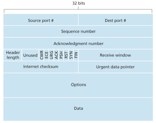
- The 32-bit sequence number field and the 32-bit acknowledgement number field are used by the TCP sender and receiver in implementing a reliable data transfer service.
- The 16-bit receiver window field is used for flow control, used to indicate the number of bytes that a receiver is willing to accept.
- The 4-bit header length field specifies the length of the TCP header in 32-bit words, the TCP header can be of variable length due to the TCP options field, typically, the options field is empty, so that the length of the typical TCP header is 20 bytes
- The optional and variable-length options field is used when a sender and receiver negotiate the maximum segment size (MSS) or as a window scaling factor for use in high-speed networks. A timestamping option is also defined.
- The flag field contains 6 bits, the ACK bit is used to indicate that the value carried in the acknowledgement field is valid; that is, the segment contains an acknowledgement for a segment that has been successfully received. The RST, SYN, and FIN bits are used for connection setup and teardown. The CWR and ECE bits are used in explicit congestion notification. Setting the PSH bit indicates that the receiver should pass the dadta to the upper layer immediately. Finally, the URG bit is used to indicate that there is data in this segment that the sending-side upper-layer entity has marked as urgent. The location of the last byte of this urgent data is indicated by the 16-bit urgent data pointer field. TCP must inform the receiving side upper layer entity when urgent data exists and pass it a pointer to the end of the urgent data.
Please elaborate on sequence numbers? TCP views data as an unstructured, but ordered, stream of bytes, TCP’s use of sequence numbers reflects this view in that sequence numbers are over the stream of transmitted bytes and not over the series of transmitted segments.
Suppose TCP in host A has 500,000 bytes to send, with MSS 1,000 bytes, TCP contructs 500 segments out of the data stream, first segment gets assigned sequence number 0, the second segment gets assigned sequence number 1,000 and so on.
The TCP is full-duplex, so that host A may be receiving data from host B while it sends data to host B, the acknowledgement number that host A puts in its segment is the sequence number of the next byte host A is expecting from host B. Suppose A has received all bytes numbered 0 through 535 from B, so host A puts 536 in the acknowledgement number field of the segment it sends to B.
In another example, suppose A has received one segment from B containing bytes 0 through 535 and another containing 900 through 1,000. Host A is still waiting for byte 536 in order to re-create B’s data stream. Thus A’s next segment to B will contain 536 in the acknowledgement number field.
Because TCP only acknowledges bytes up to the first missing byte in the stream, TCP is said to provide cumulative acknowledgments.
Note that the acknowledgment for client-to-server data is carried in a segment carrying server-to-client data; this acknowledgment is said to be piggybacked on the server-to-client data segment
Does sequence numbers start from zero? Both sides of a TCP connection randomly choose an initial sequence number, done to minimize the possibility that a segment that is still present in the network from an earlier, already-transmitted connection between two hosts is mistaken for a valid segment in a later connection between the same two hosts which also happen to be using the same port numbers as the old connection.
What does a host do when it receives out-of-order segments in a TCP connection? TCP do not impose any rules here and leave the decision up to the programmers implementing a TCP implementation. Basically two choices: either the receiver immediately discards out-of-order segments or the receiver keeps the out-of-order bytes and waits for the missing bytes to fill in the gaps.
How to set the timer here? …
Any specifics to reliable data transfer? Earlier, it was conceptually easiest to assume that an individual timer is associated with each transmitted but not yet acknowledged segment, while great in theory, timer management can require considerable overhead, thus, the recommended TCP timer management procedures use only a single transmission timer, even if there are multiple transmitted but not yet acknowledged segments.
(some steps are here brother so see some books)
Flow Control
When the TCP connection receives bytes that are correct and in sequence, it places the data in the receive buffer. The associated application process will read data from this buffer, but not necessarily at the instant the data arrives. If the application is relatively slow at reading the data, the sender can very easily overflow the connection’s receive buffer by sending too much data too quickly.
TCP provides a flow-control service to its applications to eliminate the possibility of the sender overflowing the receiver’s buffer. Flow control is thus a speed-matching service—matching the rate at which the sender is sending against the rate at which the receiving application is reading.
TCP sender can also be throttled due to congestion within the IP network; this form of sender control is referred to as congestion control.
Even though the actions taken by flow and congestion control are similar (the throttling of the sender), they are obviously taken for very different reasons.
TCP provides flow control by having the sender maintain a variable called the receive window, informally, the receive window is used to give the sender an idea of how much free buffer space is available at the receiver.
—Assume to discard out-of-order segments—
Because TCP is full-duplex, the sender at each side of the connection maintains a distinct receive window.
Suppose that Host A is sending a large file to Host B over a TCP connection. Host B allocates a receive buffer to this connection; denote its size by . From time to time, the application process in Host B reads from the buffer.
Define the variables:
- : the number of the last byte in the data stream read from the buffer by the application process in B.
- : the number of the last byte in the data stream that has arrived from the network and has been placed in the receive buffer at B.
Because TCP is not permitted to overflow the allocated buffer, we have The receive window, denoted by is set to the amount of spare room in the buffer
…
TCP Connection Management
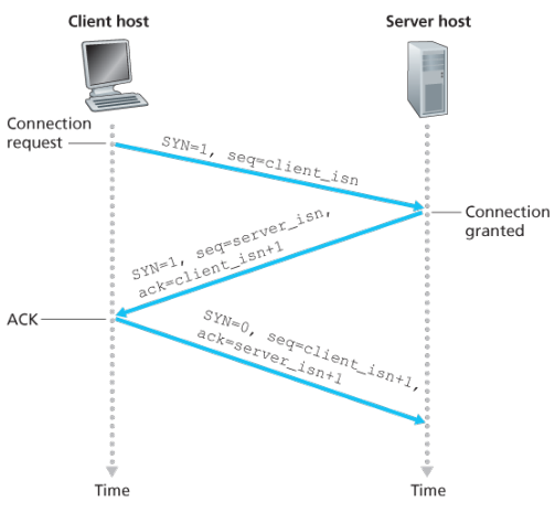
Suppose a process running in one host wants to initiate a connection with another process in another host. The client application process first informs the client TCP that it wants to establish a connection to a process in the server.
The TCP in the client then proceeds to establish a TCP connection with the TCP in the server in the following manner:
- The client-side TCP sends a special TCP segment to the server-side TCP. This special segment contains no application-layer data. But one of the flag bits in the segment’s header, the SYN bit, is set to 1. For this reason, this special segment is referred to as SYN segment. In addition, the client randomly chooses an initial sequence number () and puts this number in the sequence number field of the initial TCP SYN segment. This segment is encapsulated within an IP datagram and sent to the server.
- Once the IP datagram containing the TCP SYN segment arrives at the server host, the server extracts the TCP SYN segment from the datagram, allocates the TCP buffers and variables to the connection, and sends a connection-granted segment to the client TCP. This connection-granted segment also contains no application-layer data. First, the SYN bit is set to 1. Second, the acknowledgement field of the TCP segment header is set to . Finally, the server chooses its own initial sequence number () and puts this value in the sequence number field of the TCP segment header. In effect of saying: “I received your SYN packet to start a connection with your initial sequence number, . I agree to establish this connection. My own initial sequence number is “. The connection-granted segment is referred to as SYNACK segment.
- Upon receiving the SYNACK segment, the client also allocates buffers and variables to the connection. The client host then sends the server yet another segment; this last segment acknowledges the server’s connection-granted segment (the client does so by putting the value in the acknowledgement field of the TCP segment header.) The SYN bit is set to zero, since the connection is established. This third stage of the three-way handshake may carry client-to-server data in the segment payload.
Once these three steps have been completed, the client and server hosts can send segments containing data to each other. In each of these future segments, the SYN bit will be set to zero.
Questions related to this connection mechanism? Why is there-way handshake, as opposed to two-way handshake, needed?
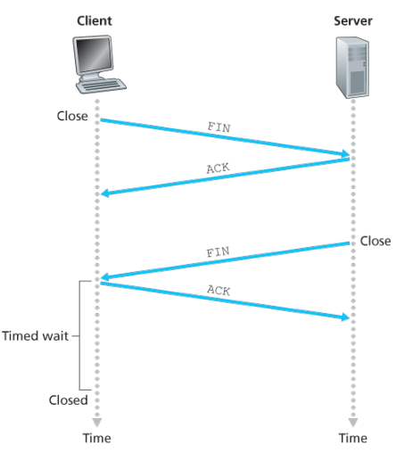
Either of the two processes participating in a TCP connection can end the connection. When a connection ends, the resources, that is, the buffers and variables in the hosts are deallocated.
As an example, suppose the client decides to close the connection, the client application process issues a close command.
- This causes the client TCP to send a special TCP segment to the server process. This special segment has a flag bit in the segment’s header, the FIN bit set to 1.
- When the sender receives this segment, it sends the client an acknowledgement segment in return. The server then sends its own shutdown segment, which has the FIN bit set to 1.
- Finally, the client acknowledges the server’s shutdown segment. At this point, all the resources in the two hosts are now deallocated.
 …Each client and server goes through states, lets see from that perspective though…
…
Congestion Control
Packet re-transmission treats a symptom of network congestion (the loss of a specific transport-layer segment) but does not treat the cause of network congestion - too many sources attempting to send data at too high a rate.
To treat the cause of network congestion, mechanisms are needed to throttle senders in the face of network congestion.
The approach taken by TCP is to have each sender limit the rate at which it sends traffic into its connection as a function of perceived network congestion. If a sender perceives that there is little congestion on the path between itself and the destination, then the TCP sender increases its send rate; if the sender perceives that there is congestion along the path, then the sender reduces its send rate.
But this approach raises three questions. First, how does a TCP sender limit the rate at which it sends traffic into its connection? Second, how does a TCP sender perceive that there is congestion on the path between itself and the destination? And third, what algorithm should the sender use to change its send rate as a function of perceived end-to-end congestion?
The TCP congestion control mechanism operating at the sender keeps track of an additional variable, the congestion window, denoted by , imposes a contrainst on the rate at which a TCP sender can send traffic to the netwwrk.
Define a loss event at a TCP sender as the occurence of either a timeout or the receipt of three duplicate ACKs from the receiver. When there is excessive congestion, then one or more router buffers along the path overflows, causing a datagram contaning a TCP segment to be droped. The dropped datagram, in turn, result sin a loss event at the sender - either a timeout or the receipt of three duplicate ACKs - which is taken by the sender to be an indication of congestion on the sender-to-receiver path.
Lets consider the more optimistic case when the network is congestion-free, that is, when a loss event does not occur. In this case, acknowledgements for previously unacknowledged segments will be received at the TCP sender, TCP will take the arrival of these acknowledgements as an indication that all is well - and use acknowledgements to increase its congestion window size (and hence its tranmissionr ate).
- Slow start: When a TCP connnection begins, the value of is typically initialized to a small value of 1 MSS resulting in an tiniitla sending rate of roughly MSS/RTT. In the slow-start state, the value of begins at 1 MSS and inrease by 1MSS every time a transmitted semgnet is first acknowledged. First if there is a loss event indiciated by a timeout, the TCP sender sets the value of cwnd to 1 and begins the slow start process anew, it also sets the value of a second state variable to - half of the value of congestion window when congestion was detected. When the value of equals , slow starts ends and TCP transitions into congestion avoidance mode.
- Congestion avoidance: On entry to congestion-avoidance state, the value of is apprxoimately half its value when congestion was last encountered - congestion could be just around the corner. Thus rather than doubling the value of every RTT. TCP adopts a more conservative approach and increaes the value of by just a single MSS every RTT.
(earlier ko chai increase by each ack received thiyo jun chai corresponding to doublign each RTT)
TCP’s congestion avoidance algorithm behaves the same when a timeout occurs. As in the case of slow start: The value of cwnd is set to 1 MSS, and the value of ssthresh is updated to half the value of cwnd when the loss event occurred. Recall, however, that a loss event also can be triggered by a triple duplicate ACK event.
In this case, the network is continuing to deliver segments from sender to receiver (as indicated by the receipt of duplicate ACKs). So TCP’s behavior to this type of loss event should be less drastic than with a timeout-indicated loss: TCP halves the value of cwnd (adding in 3 MSS for good measure to account for the triple duplicate ACKs received) and records the value of ssthresh to be half the value of cwnd when the triple duplicate ACKs were received. The fast-recovery state is then entered.
(whatever bro there is some shit)
- Fast recovery: In fast recovery, the value of is increased by 1 MSS for every duplicate ACK received for the missing segment that caused TCP to enter the fasts-recovery state.
principles of congestion control
…
TCP Specific Control
…
(this is some weird topic inserted here)
Quality of Service
Multimedia applications often need a minimum throughput and maximum latency to work. …
Before the network can make QoS guarantees, it must know what traffic is being guaranteed. Bursts of traffic are more difficult to handle than constant-rate traffic because they can fill buffers and cause packets to be lost.
Traffic shaping is a technique for regulating the average rate and burstiness of a flow of data that enters the network. The goal is to allow applications to transmit a wide variety of traffic that suits their needs, including some bursts, yet have a simple and useful way to describe the possible traffic patterns to the network.
Traffic shaping reduces congestion and thus helps the network live up to its promise. However, to make it work, there is also the issue of how the provider can tell if the customer is following the agreement and what to do if the customer is not.
Leaky bucket
The leaky bucket is a traffic shaping technique based on the analogy of a bucket with a small hole in the bottom where no matter the rate at which water enters the bucket, the outflow is at constant rate, and zero when the bucket is empty, also once the bucket is fully to capacity B, any additional water entering it spills over the side and is lost.
This bucket can be used to shape or police packets entering the network, conceptually each host is connected to the network by a interface containing a leaky bucket. To send a packet into the network, it must be possible to put more water into the bucket, if a packet arrives when the bucket if full the packet must either be queued until enough water leaks out to hold it or be discared.
The former might happen at a host shaping its traffic for the network as part of the OS, the latter might happen in hardware at a provider network that is policing traffic entering the network.
Implementation:
In one version the bucket is a counter or variable separate from the flow of traffic or schedule of events. This counter is used only to check that the traffic or events conform to the limits: The counter is incremented as each packet arrives at the point where the check is being made or an event occurs, which is equivalent to the way water is added intermittently to the bucket. The counter is also decremented at a fixed rate, equivalent to the way the water leaks out of the bucket. As a result, the value in the counter represents the level of the water in the bucket. If the counter remains below a specified limit value when a packet arrives or an event occurs, i.e. the bucket does not overflow, that indicates its conformance to the bandwidth and burstiness limits or the average and peak rate event limits. This version is referred to here as the leaky bucket as a meter.
Token Bucket
A different but equivalent fomrulation is to imagine the network as a bucket that is being filled with a tap running at rate R and the bucket has a capacity of B, now to send a packet we must able to take water, or tokens, out of the bucket rather than putting into the bucket. No more than a fixed number of tokens can accumuate in the bucket, and if the bucket is empty, we must wait until more tokens arrive before we can send another packet.
… Leaky and token buckets limit the long-term rate of a flow but allow short-term bursts up to a maximum regulated lenghth to pass through unaltered and without suffering nay artificial delays. Large burts will be smothened by a leaky bucket traffic shaper to reduce congestion in the network.
Calculating the length of the maximum burst is slightly tricky because while the burst is being output, more tokens arrive. If we call the burst length sec., then the maximum output rate bytes/sec, the token capacity bytes, and token arrival rate bytes/sec, we can see that burst contains a maximum of bytes. We also know that the number of bytes in a maximum speed burst of length seconds is . We have, Solve for S.
----Example---- Suppose a computer can produce data at upto 1000 Mbps and that the first link of the network also runs at this speed.
Say 125MB/s for 125msec and 25MB/s for 250msec generated by the PC. Now suppose that the routers can accept data at the top speed only for short intervals until their buffers fill up. The buffer size is 9600KB, smaller than the traffic burst.
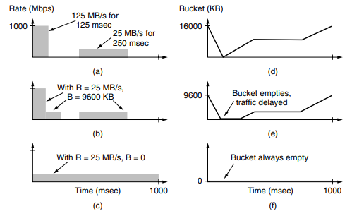 For long intervals, the routers work best at rates not exceeding 200 Mbps say, because this is all the bandwidth given to the customer. The implication is that if traffic is sent in this pattern, some of it will be dropped in the network because it does not fit into the buffers at routers
To avoid this packet loss, can shape the traffic at the host with a token bucket, if we use a rate, R, of 200 Mbps, and a cpacity of 9600 KB, the traffic will fall within the network can handle.
The host can send full throttle at 1000 Mbps for a short while until it has drained the bucket. Then it has to cut back to 200 Mbps until the burst has been sent. The effect is to spread out the burst over time because it was too large to handle all at once. …