The basic service of link layer is to move a datagram from one node to an adjacent node over a single communication link, the details of the provided service can vary from one link-layer protocol to the next. Possible services that can be offered by a link-layer protocol include:
Framing
Almost all link-layer protocols encapsulate each network-layer datagram within a link-layer before transmission over the link. A frame consists of a data field, in which the network-layer datagram is inserted, compute a short token called checksum for each frame, and include the checksum in the frame when it is transmitted. The structure of the frame is specified by the link-layer protocol.
A good design must make it easy for a receiver to find the start of new frames while using little of the channel bandwidth.
-
Byte count: The first framing method uses a field in the header to specify the number of bytes in the frame. When the data link layer at the destination sees the byte count, it knows how many bytes follow and hence where the end of the frame is. The trouble with this algorithm is that count can be garbled by a transmission error. For example, if the byte count of 5 in a frame becomes a 7 due a single bit flip, the destination will get out of synchronization.
-
Flag bytes with byte stuffing: The second framing method gets around the problem of resynchronization after an error by having each frame start and end with special bytes. Often the same byte, called a flag byte, is used as both the starting and ending delimiter. Two consecutive flag bytes indicate the end of one frame and the start of the next. Thus, if the receiver ever loses synchronization it can just search for two flag bytes to find the end of the current frame and the start of the next frame. It may happen that the flag byte occurs in the data, especially when binary data such as photographs or songs are being transmitted. This situation would interfere with the framing. One way to solve this problem is to have the sender’s data link layer insert a special escape byte (ESC) just before each accidental flag byte in the data. PPP.
-
Flag bits with bit stuffing: The third method of delimiting the bit stream gets around a disadvantage of byte stuffing, which is that it is tied to the use of 8-bit bytes. Framing can be also be done at the bit level, so frames can contain an arbitrary number of bits made up of units of any size. . It was developed for the once very popular HDLC (Highlevel Data Link Control) protocol. Each frame begins and ends with a special bit pattern, 01111110 or 0x7E in hexadecimal. This pattern is a flag byte. Whenever the sender’s data link layer encounters five consecutive 1s in the data, it automatically stuffs a 0 bit into the outgoing bit stream. This bit stuffing is analogous to byte stuffing, in which an escape byte is stuffed into the outgoing character stream before a flag byte in the data.
-
Physical layer coding violations: The last method of framing is to use a shortcut from the physical layer. The encoding of bits as signals often includes redundancy to help the receiver. This redundancy means that some signals will not occur in regular data. For example, in the 4B/5B line code 4 data bits are mapped to 5 signal bits to ensure sufficient bit transitions. This means that 16 out of the 32 signal possibilities are not used. We can use some reserved signals to indicate the start and end of frames.
Access Control
A medium access control (MAC) protocol specifies the rules by which a frame is transmitted onto the link. . For point-to-point links that have a single sender at one end of the link and a single receiver at the other end of the link, the MAC protocol is simple (or nonexistent)—the sender can send a frame whenever the link is idle. The more interesting case is when multiple nodes share a single broadcast link—the so-called multiple access problem. Here, the MAC protocol serves to coordinate the frame transmissions of the many nodes.
Error Control
How to make sure all frames are eventually delivered to the network layer at the destination and in the proper order?
(Principles of Reliable Transfer)
- The usual way to ensure reliable delivery is to provide the sender with some feedback about what is happening at the other end of the line. Bit errors are introduced by signal attenuation and electromagnetic noise. Because there is no need to forward a datagram that has an error, many link-layer protocols provide a mechanism to detect such bit errors. This is done by having the transmitting node include error-detection bits in the frame, and having the receiving node perform an error check. (Error Control)
- Typically, the protocol calls for the receiver to send back special control frames bearing positive or negative acknowledgements about the incoming frames. If the sender receives a positive acknowledgement about a frame, it knows the frame has arrived safely.
- On the other hand, a negative acknowledgement means that something has gone wrong and the frame must be transmitted again.
- An additional complication comes from the possibility that hardware troubles may cause a frame to vanish completely (e.g., in a noise burst). In this case, the receiver will not react at all, since it has no reason to react. Similarly, if the acknowledgement frame is lost, the sender will not know how to proceed. It should be clear that a protocol in which the sender transmits a frame and then waits for an acknowledgement, positive or negative, will hang forever if a frame is ever lost due to, for example, malfunctioning hardware or a faulty communication channel. This possibility is dealt with by introducing timers into the data link layer. When the sender transmits a frame, it generally also starts a timer. The timer is set to expire after an interval long enough for the frame to reach the destination, be processed there, and have the acknowledgement propagate back to the sender.
- However, when frames may be transmitted multiple times there is a danger that the receiver will accept the same frame two or more times and pass it to the network layer more than once. To prevent this from happening, it is generally necessary to assign sequence numbers to outgoing frames, so that the receiver can distinguish retransmissions from originals.
Flow Control
Another important design issue that occurs in the data link layer is what to do with a sender that systematically wants to transmit frames faster than the receiver can accept them. This situation can occur when the sender is running on a fast, powerful computer and the receiver is running on a slow, low-end machine.
Two approaches are commonly used. In the first one, feedback-based flow control, the receiver sends back information to the sender giving it permission to send more data, or at least telling the sender how the receiver is doing. In the second one, rate-based flow control, the protocol has a built-in mechanism that limits the rate at which senders may transmit data, without using feedback from the receiver.
Examples of link-layer protocols: (PPP)
MAC Address
Host and routers have link-layer addresses. You might be asking why in the world do we need to have addresses at both the network and link layers?
In truth, it is not hosts and routers that have link-layer addresses but rather their adapters i.e. network interfaces that have link-layer addresses, a host or router with multiple network interfaces will thus have multiple link layer addresses associated with it, just as would have multiple IP addresses associated with it.
However, the link layer switches do not have link layer addresses associated with it because the job of the link-layer switch is to carry datagrams between hosts and routers; carries datagrams transparently, ie, without the host or router having to explicitly address the frame to the intervening switch.
A link layer address is variously called LAN address, is 6 bytes long, giving possible MACs. Although designed to be permanent, now possible to change an adapter’s MAC address via software. When a company wants to manufacture adapters, it purchases a chunk of the addresses space consisting of addresses for a nominal fee. IEEE allocates the chunk of addresses by fixing the first bits of a MAC address.
An adapter’s MAC address has as opposed to a hierarchical flat structure and does not change no matter where the adapter goes. A laptop with an Ethernet interface always has the same MAC address, no matter where the computer goes. A smartphone with an 802.11 interface always has the same MAC address, no matter where the smartphone goes. Recall that, in contrast, IP addresses have a hierarchical structure (that is, a network part and a host part), and a host’s IP addresses needs to be changed when the host moves, i.e., changes the network to which it is attached.
When an adapter wants to send a frame to some destination adapter, the sending adapter inserts the destination adapter’s MAC address into the frame and then sends the frame into the LAN. When an adapter receives a frame, it will check to see whether the destination MAC address in the frame matches its own MAC address. If there is a match, the adapter extracts the enclosed datagram and passes the datagram up the protocol stack. If there isn’t a match, the adapter discards the frame, without passing the network-layer datagram up.
However, sometimes a sending adapter does want all the other adapters on the LAN to receive and process the frame it is about to send. In this case, the sending adapter inserts a special MAC broadcast address into the destination address field of the frame. For LANs that use 6-byte addresses (such as Ethernet and 802.11), the broadcast address is a string of 48 consecutive 1s (that is, FF-FF-FF-FF-FFFF in hexadecimal notation).
ARP
Because there are both network-layer addresses, for example, IP addresses and link-layer addresses that is, MAC addresses, there is a need to translate between them. For the Internet, this is the job of Address Resolution Protocol (ARP).
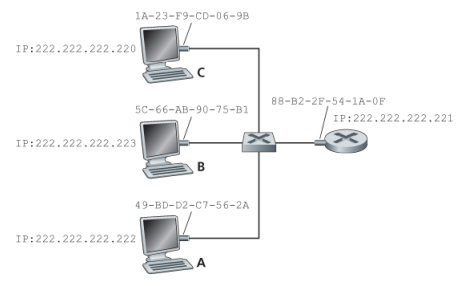
Assume that whenever a switch receives a frame on one interface, it forwards on all of its other interfaces.
Suppose that the host with IP 222.222.222.220 wants to send an IP to host 222.222.222.222. Here both the source and destination are in the same subnet. To send a datagram, the source must give its adapter, not only the IP datagram but also the MAC address for destinaiton 222.222.222.222. The sending adapter then will construct a link-layer frame containing the destination MAC and send the frame into the LAN.
An ARP module in the sending host takes any IP address on the same LAN as input, and returns the corresponding MAC address. In the example at hand, sending host 222.222.222.220 provides its ARP module the IP address 222.222.222.222, and the ARP module returns the corresponding MAC address 49-BD-D2-C7-56-2A.
In many ways it is analogous to DNS, which resolves host names to IP addresses. However, one important difference between the two resolvers is that DNS resolves host names for hosts anywhere in the Internet, whereas ARP resolves IP addresses only for hosts and router interfaces on the same subnet.
The ARP table also contains a timeto-live (TTL) value, which indicates when each mapping will be deleted from the table. Note that a table does not necessarily contain an entry for every host and router on the subnet; some may have never been entered into the table, and others may have expired.
Now suppose that host 222.222.222.220 wants to send a datagram that is IP-addressed to another host or router on that subnet. The sending host needs to obtain the MAC address of the destination given the IP address. This task is easy if the sender’s ARP table has an entry for the destination node. But what if the ARP table doesn’t currently have an entry for the destination? In particular, suppose 222.222.222.220 wants to send a datagram to 222.222.222.222. In this case, the sender uses the ARP protocol to resolve the address. First, the sender constructs a special packet called an ARP packet. An ARP packet has several fields, including the sending and receiving IP and MAC addresses. Both ARP query and response packets have the same format. The purpose of the ARP query packet is to query all the other hosts and routers on the subnet to determine the MAC address corresponding to the IP address that is being resolved.
Returning to our example, 222.222.222.220 passes an ARP query packet to the adapter along with an indication that the adapter should send the packet to the MAC broadcast address, namely, FF-FF-FFFF-FF-FF. The adapter encapsulates the ARP packet in a link-layer frame, uses the broadcast address for the frame’s destination address, and transmits the frame into the subnet.
The frame containing the ARP query is received by all the other adapters on the subnet, and (because of the broadcast address) each adapter passes the ARP packet within the frame up to its ARP module. Each of these ARP modules checks to see if its IP address matches the destination IP address in the ARP packet. The one with a match sends back to the querying host a response ARP packet with the desired mapping. The querying host 222.222.222.220 can then update its ARP table and send its IP datagram, encapsulated in a link-layer frame whose destination MAC is that of the host or router responding to the earlier ARP query.
What Is ARP, a link layer or network layer protocol? ARP is encapusalted within a link layer frame and thus lies architecturally above the link layer, however an ARP packet has fields containing link layer addresses, but also contains network layer addresses and is arugably a netwok layer. In the end, ARP is probably best considered a protocol that straddles the bourndary between the link and network layers - not fitting neatly into the simple protocol stack, usch are complextities of real world
But now let’s look at the more complicated situation when a host on a subnet wants to send a network-layer datagram to a host off the subnet (that is, across a router onto another subnet).
Now let’s examine how a host on Subnet 1 would send a datagram to a host on Subnet 2. Specifically, suppose that host 111.111.111.111 wants to send an IP datagram to a host 222.222.222.222.
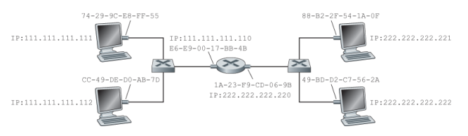
The sending host passes the datagram to its adapter, as usual. But the sending host must also indicate to its adapter an appropriate destination MAC address. What MAC address should the adapter use? One might be tempted to guess that the appropriate MAC address is that of the adapter for host 222.222.222.222, namely, 49-BD-D2-C7-56-2A. This guess, however, would be wrong! If the sending adapter were to use that MAC address, then none of the adapters on Subnet 1 would bother to pass the IP datagram up to its network layer, since the frame’s destination address would not match the MAC address of any adapter on Subnet 1. The datagram would just die and go to datagram heaven.
The datagram must first be sent to the router interface 111.111.111.110, which is the IP address of the first-hop router on the path to the final destination. Thus, the appropriate MAC address for the frame is the address of the adapter for router interface 111.111.111.110, namely, E6-E9-00-17- BB-4B. How does the sending host acquire the MAC address for 111.111.111.110? By using ARP, of course!