What is the internet?
First, we can describe the nuts and bolts of the internet, that is, the basic hardware and software components that make up the Internet.
Second, we can describe the Internet in terms of a networking infrastructure that provides services to distributed applications.
Nuts-and-Bolts Description
Internet is a network, I know, but of what? The Internet is a computer network that interconnects billions of computing devices throughout the world. Increasingly, nontraditional internet things such as laptops, smartphones, tablets, TVs, gaming consoles, thermostats, home appliances, watches, eye glasses are being connected to the Internet. In Internet jargon, all of these devices are called hosts or end systems
End systems connected to one another? End systems are connected together by a network of communication links and packet switches. There are many types of communication links which are made up of different types of physical media, including coaxial cable, copper wire, optical fiber, and radio spectrum. Packet switches come in many shapes and flavors, but the two most prominent types in today’s Internet are routers and link-layer switches. Different links can transmit data at different rates, with the transmission rate of a link measured in bits/second.
How they communicate then? When one end system has data to send to another end system, the sending end system segments the data and adds header bytes to each segment. The resulting packages of information, known as packets in the jargon of computer networks, are then sent through the network to the destination end system, where they are reassembled into the original data.
Tell me more about internals of what’s connecting end systems. End systems access the Internet through Internet Service Providers (ISPs), including residential ISPs such as local cable or telephone companies; corporate ISPs; university ISPs; ISPs that provide WiFi access in airports, hotels, coffee shops, and other public places; and cellular data ISPs, providing mobile access to our smartphones and other devices. Each ISP is in itself a network of packet switches and communication links. ISPs provide a variety of types of network access to the end systems, including residential broadband access such as cable modem or DSL, high-speed local area network access, and mobile wireless access. ISPs also provide Internet access to content providers, connecting Web sites and video servers directly to the Internet.
How are these all end systems and ISPs in coordination? The Internet is all about connecting end systems to each other, so the ISPs that provide access to end systems must also be interconnected. These lower-tier ISPs are interconnected through national and international upper-tier ISPs such as Level 3 Communications, AT&T, Sprint, and NTT. An upper-tier ISP consists of high-speed routers interconnected with high-speed fiber-optic links. Each ISP network, whether upper-tier or lower-tier, is managed independently, runs the IP protocol, and conforms to certain naming and address conventions.
Services Description
In addition to traditional applications such as e-mail and Web surfing, Internet applications include mobile smartphone and tablet applications, including Internet messaging, mapping with real-time road-traffic information, music streaming from the cloud, movie and television streaming, online social networks, video conferencing, multi-person games, and location-based recommendation systems.
The applications are said to be distributed applications, since they involve multiple end systems that exchange data with each other.
End systems attached to the Internet provide a socket interface that specifies how a program running on one end system asks the Internet infrastructure to deliver data to a specific destination program running on another end system. This Internet socket interface is a set of rules that the sending program must follow so that the Internet can deliver the data to the destination program.
The Network Edge
End systems are also referred to as hosts because they host that is, run application programs such as a Web browser program, a Web server program, an e-mail client program, or an e-mail server program. Hosts are sometimes further divided into two categories: clients and servers. Informally, clients tend to be desktop and mobile PCs, smartphones, and so on, whereas servers tend to be more powerful machines that store and distribute Web pages, stream video, relay e-mail, and so on. Today, most of the servers from which we receive search results, e-mail, Web pages, and videos reside in large data centers.
Having considered the applications and end systems at the edge of the network, the network that physically connects an end system to the first router (also known as the “edge router”) on a path from the end system to any other distant end system are the access networks.
The access ISP does not have to be a telco or cable company; instead it can be, for example, a university providing Internet access to student, staff and faculty. But connecting end users and content providers into an access ISP is only a small piece of solving the puzzle of connecting the billions of end systems that make up the Internet. To complete this puzzle, the access ISPs themselves must be interconnected which is done by creating a network of networks.
(The Edge Network) (see: conversion techniques, information theory;)
What is even a protocol? All activity in the Internet that involves two or more communicating remote entities is governed by a protocol. For example, hardware-implemented protocols in two physically connected computers control the flow of bits on the wire between the two network interface cards; congestion-control protocols in end systems control the rate at which packets are transmitted between sender and receiver; protocols in routers determine a packet’s path from source to destination.
A protocol defines the format and the order of messages exchanged between two or more communicating entities, as well as the actions taken on the transmission and/or receipt of a message or other event.
The Network Core
Having examined the Internet’s edge, now delve more deeply inside the network core - the mesh of packet switches (see switching:) and links that interconnects the Internet’s end systems. Much of evolution of Internet is driven by economics and national policy rather than by performance considerations. Let’s incrementally build a series of network structures, with each new structure being a better approximation of the complex internet we have today.
Naive approach (mesh ISPs) One naive approach would be to have each access ISP directly connect with every other access ISP, such a mesh design is, of course, much too costly for the access ISPs, as it would require each access ISP to have a separate communication link to each of the hundreds of thousands of other access ISPs all over the world.
Structure 1 (start ISPs) Our first network structure, interconnects all of the access ISPs with a single global transit ISP, which is a network of routers and communication links that not only spans the globe, but also has at least one router near each of hundreds of thousands of access ISPs. It would be very costly for the global ISP to build such an extensive network. To be profitable, it would naturally charge each of the access ISPs for connectivity, with the pricing reflecting the amount of traffic an access ISP exchanges with the global ISP.
Structure 2 Now If some company builds and operates a global transit ISP that is profitable then it is natural for other companies to build their own global transit ISPs and compete with the original global transit ISP which leads to another structure that consists of hundreds of thousands of access ISPs and multiple global transit ISPs. However, the global transit ISPs themselves must interconnect: otherwise access ISPs connected to one of the global transit providers would not be able to communicate with access ISPs connected to other global transit providers. This is a two-tier hierarchy with global transit providers residing at the top tier and access ISPs at the bottom tier. This assumes that global transit ISPs are not only capable of getting close to each and every access ISP, but also find it economically desirable to do so.
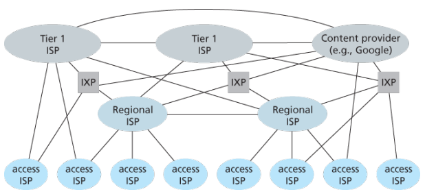
Structure 3 In reality, although some ISPs do have impressive global coverage and do directly connect with many access ISPs, no ISP has presence in each and every city in the world. Instead, in any given region, there may be a regional ISP to which the access ISPs in the region connect. Each regional ISP then connects to tier-1 ISPs. Tier-1 ISPs are similar to our (imaginary) global transit ISP; but tier-1 ISPs, which actually do exist, do not have a presence in every city in the world. There are approximately a dozen tier-1 ISPs, including Level 3 Communications, AT&T, Sprint, and NTT. Each regional ISP then connects to tier-1 ISPs. Tier-1 ISPs are similar to our (imaginary) global transit ISP; but tier-1 ISPs, which actually do exist, do not have a presence in every city in the world. There are approximately a dozen tier-1 ISPs, including Level 3 Communications, AT&T, Sprint, and NTT. An access ISP can also connect directly to a tier-1 ISP, in which case it pays the tier-1 ISP. To further complicate matters, in some regions, there may be a larger regional ISP (possibly spanning an entire country) to which the smaller regional ISPs in that region connect; the larger regional ISP then connects to a tier-1 ISP.
Structure 4 The amount that a customer ISP pays a provider ISP reflects the amount of traffic it exchanges with the provider. To reduce these costs, a pair of nearby ISPs at the same level of the hierarchy can peer, that is, they can directly connect their networks together so that all the traffic between them passes over the direct connection rather than through upstream intermediaries. When two ISPs peer, it is typically settlement-free, that is, neither ISP pays the other. As noted earlier, tier-1 ISPs also peer with one another, settlement-free. Along these same lines, a third-party company can create an Internet Exchange Point (IXP), which is a meeting point where multiple ISPs can peer together. An IXP is typically in a stand-alone building with its own switches. There are over 400 IXPs in the Internet today.
Structure 5 We now finally arrive at Network Structure 5, which describes today’s Internet builds on top of Network Structure 4 by adding content-provider networks. Google is currently one of the leading examples of such a content-provider network. The Google data centers are all interconnected via Google’s private TCP/IP network, which spans the entire globe but is nevertheless separate from the public Internet. Importantly, the Google private network only carries traffic to/from Google servers. The Google private network attempts to “bypass” the upper tiers of the Internet by peering (settlement free) with lower-tier ISPs, either by directly connecting with them or by connecting with them at IXPs. However, because many access ISPs can still only be reached by transiting through tier-1 networks, the Google network also connects to tier-1 ISPs, and pays those ISPs for the traffic it exchanges with them. By creating its own network, a content provider not only reduces its payments to upper-tier ISPs, but also has greater control of how its services are ultimately delivered to end users.
Layered Architecture
The Internet is an extremely complicated system. We have seen that there are many pieces to the Internet: numerous applications and protocols, various types of end systems, packet switches, and various types of link-level media. Given this enormous complexity, is there any hope of organizing a network architecture, or at least our discussion of network architecture?
- A layered architecture allows us to discuss a well-defined, specific part of a large and complex system.
- This simplification itself is of considerable value by providing modularity, making it much easier to change the implementation of the service provided by the layer. As long as the layer provides the same service to the layer above it, and uses the same services from the layer below it, the remainder of the system remains unchanged when a layer’s implementation is changed.
- For large and complex systems that are constantly being updated, the ability to change the implementation of a service without affecting other components of the system is another important advantage of layering.
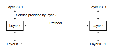
To provide structure to the design of network protocols, network designers organize protocols—and the network hardware and software that implement the protocols—in layers.
- The purpose of each layer is to offer certain services to the higher layers while shielding those layers from the details of how the offered services are actually implemented.
When layer on one machine carries on a conversation with layer on another machine, the rules and conventions used in this conversation are collectively known as the layer protocol. Between each pair of adjacent layers is an interface that defines which primitive operations and services the lower layer makes available to the upper one.
When network designers decide how many layers to include in a network and what each one should do, one of the most important considerations is defining clean interfaces between the layers. Minimizing the amount of information that must be passed between layers and clear cut interfaces make it simple to replace one layer with a completely different protocol or implementation because all that is required of the new protocol is that it offer exactly the same set of services to its upstairs neighbors as the earlier one did. It is widely common that different hosts use different implementation of the same protocol often written by different companies.
Services vs protocols
A service is a set of primitives that a layer provides to the layer above it but says nothing about how these operations are implemented. A protocol is a set of rules governing the format and meaning of the messages that are exchanged by the peer entities within a layer. Entities use protocols to implement their service definitions, are free to change their protocols at will, provided that they do not change the service visible to their users. Again services relate to the interfaces between layers in contrast, protocols relate to the messages sent between peer entities on different machines. The service and the protocol are completely decoupled concepts.
 (analogy service being abstract data type while protocol relates to implementation of it)
Layers can offer two different types of services to the layers above them; Connection-oriented service is modeled after the telephone system to use which the service user first establishes a connection, uses the connection, and then releases the connection. Essential aspect of a connection is that it acts like a tube: the sender pushes objects in at one end, and the receiver takes them out at the other end. In most cases the order is preserved so that the bits arrive in the order they were sent. In some cases when a connection is established, the sender, receiver and subnet? conduct a negotiation about the paramters to be used such as maximum message size, quality of service required, and other issues. In contrast, connectionless is modeled after the postal system, each message carries the full destination address and each one is routed through the intermediate nodes inside the system independent of all the subsequent messages
Models
OSI Based on a proposal developed by the ISO as a first step toward international standardization of the protocols used in the various layers
Is called Open Systems Interconnection because it deals with connecting open systems that are open for communication with other systems
Does not specify the exact services and protocols to be used in each layer, just tells what each layer should do
-
Physical layer
- (gpt) Handles the physical transmission of data over the network, including encoding, signaling, and hardware specifications.
- (wiki) Transmission and reception of raw bit streams over a physical medium.
- Have to do with making sure that when one side sends a 1 bit it is received by the other side as a 1 bit, not as 0 bit.
- Typical questions here are what electrical signals should be used to represent a 1 and a 0, how many nanoseconds a bit lasts, whether transmission may proceed simultaneously in both directions, how the initial connection is established, how it is torn down when both sides are finished, how many pins the network connector has, and what each pin is used for
- Largely deal with mechanical, electrical, and timing interfaces, as well as the physical transmissin medium, which lies below the physical layer.
-
Data-link layer:
- (gpt) Provides reliable point-to-point and local data transmission, framing, error detection and correction, and flow control
- (wiki) Transmission of data frames between two nodes connected by a physical layer
- Transform a raw transmission facility into a line that appears free of undetected transmission errors by having the sender break up the input data into dataframes typically a few hundred or a few thousand bytes and transmit the frames sequentially.
- Typical questions here are how to keep a fast transmitter from drowning a slow receiver in data how to control access to shared channel
-
Network layer:
- (gpt) Manages addressing, routing, and logical transmission of data packets between different networks
- (wiki) structuring and managing a multi-node network including addressing, routing and traffic control
- Typical questions are how packets are routed from source to destination; can be based on static tables that are wired into the network and rarely changed or more often can be updated automatically to avoid failed components how to handle congestion so quality of service (delay, transit time, jitter) is also a network layer issue how to overcome the hetergenous addressing across networks
-
Transport layer:
- (gpt) Ensures reliable delivery of data between sytems, including segmentaion, reassembly, error recover, and flow control
- (wiki) Reliable transmission of data segments between points on a network including segmentation, acknowledgement and multiplexing
- Basic function is to accept data from above it split it into smaller unit if need be, pass these to the network layer and ensure that all the pieces arrive correctly at the other end
-
Session layer:
- (gpt) Establishes, manages, and terminates session between applications, allowing them to communicate and synchronize
-
Presentation layer:
- (gpt) Handles data representation, encryption, compression, and protocol conversion to ensure compatibility between different systems
-
Application layer:
- (gpt) Provides network services to user applications, enabling functions such as file transfer, email, remote access, and browsing
TCP/IP
ARPANET, and its successor worldwide Internet connected hundreds of universities and government installations using leased telephone lines, when satellite and radio networks were added later, the existing protocols had trouble inter-networking with them, so a new reference architecture was needed.
From nearly the beginning, the ability to connect multiple networks in a seamless way was one of the major design goals, the architecture became known as TCP/IP reference model, after its two primary protocols.
-
The Link
- Led to the choice of a packet-switching network based on a connectionless layer that runs across different networks
- It is not a layer at all in the normal sense but rather an interface between hosts and transmission links which describe what links must do to meet the needs of the connectionless internet layer
- Services provided by the link layer depend on the specific link-layer protocol that is employed over the link, some link-layer protocol provide reliable delivery, from transmitting node, over one link, to receiving node, this reliable delivery is different from the reliable delivery service of TCP which provides reliable delivery from one end system to another
- Examples of link layer protocols include cable’s DOCSIS, Ethernet, WiFi
- As datagrams typically need to traverse several links to travel from source to destination, a datagram may be handled by different link-layer protocols at different links along its route.
-
The Internet:
- Job is to permit hosts to inject packets into any network and have them travel independently to the destination potentially on a different networks
- May even arrive completely different order than they were sent in which case it is the job of higher layers to rearrange them if in-order delivery is desired
- Defines an official packet format and protocol called IP plus a companion protocol called ICMP that helps it function
- Packet routing is clearly a major issue as is congestion though IP has not proven effective at avoiding congestion
- The Internet’s network layer is responsible for moving network-layer packets known as datagrams from one host to another.
- The Internet’s network layer includes the celebrated IP protocol which defines the fileds in the datagram as well as how the end systems and routers act on these fields.
- The Internet’s network layer also contains routing protocols that determine the routes that datagrams take between sources and destinations.
- There is only one IP protocol while many routing protocols.
-
The Transport:
- Designed to allow peer entities on the source and destination hosts to carry on a conversation
- TCP is a reliable connection-orietend protocl that allows a byte stream originating on onoe machine to be delivered without error on any other machine in the internet
- It segments the incoming byte stream into discrete messages and passes each one on to the internet layer
- At the destination, the receiving TCP process reassembles the received messages into the outout stream
- Also handles flow control to make sure a fast sender cannot swampt a slow receiver with more messages than it can handle
- UDP is an unreliable, connection-less protocol for applications that do not want TCP’s sequencing or flow control and wish to provide their own
- Also widely used for one-shot client-server-type request-reply queries and applications in which prompt delivery is more important than accurate delivery such as transmitting speech of video
- Internet’s transport layer transport application-layer messages between application endpoints
- In Internet there are two transport protocols, TCP and UDP, either of which can transport messages
- TCP provides a connection-oriented service to its application which includes guaranteed delivery of application-layer messages to the destination and flow control i.e. sender/receiver speed matching
- TCP also breaks long messages into shorter segments and provides a congestion-control mechanism
- The UDP protocol provides a connection-less service to its application, which is a no-frills that provides no reliability, no flow control, and no congestion control
- Transport-layer packets are known as a segment
-
The Application
- Applications simply include any session and presentation function that they require
- Contains all the higher-level protocols; early ones included TELNET, FTP and SMTP, many other protocls have been added to these over years including DNS, HTTP and RTP
- Applicatioon layer is where network applications and their application-layer protocols reside, inlcudes many protocols, such as the HTTP protocol (which provdies for Web document request and transfer), SMTP (which provides for the transfer or emails), and FTP (whch provides for the transfer of of files between two end systems)
- Certain network functions such as the translation of human-friendly names for Internet end systems like … to 32-bit network address are also done with the help of a specific application-layer protocol namely DNS
- An application-layer protocol is distributed over multiple end systems, with the application in one end system using the protocol to exchange packets of information with the application in another end system
Differences
- An obvious difference between the two models is the number of layers: the OSI model has seven layers and the TCP/IP model has four. Both have (inter)network, transport, and application layers, but the other layers are different.
- Distinction between concepts: The biggest contribution of the OSI model is that it makes the distinction between the concepts of services, interfaces and protocols explicit. Each layer performs some services for the layer above it. The service definition tells what the layer does. A layer’s interface tells the processes above it how to access it. Finally, the peer protocols used in a layer are the layer’s own business. The TCP/IP did not originally distinguish between services, interfaces and protocols. For example, the only real services offered by the Internet layer are SEND IP PACKET and RECEIVE IP PACKET.
- Bias towards protocols: The OSI reference model was devised before the corresponding protocols were invented. This ordering meant that the model was not biased toward one particular set of protocols. With TCP/IP the reverse was true: the protocols came first, and the model was really just a description of the existing protocols. The only trouble was that the model did not fit any other protocol stacks.
- Downsides: The downside of OSI ordering was that the designers did not have much experience with the subject and did not have a good idea of which functionality to put in which layer. For example, the data link layer originally dealt with only PPP networks, when broadcast networks came around, a new sub-layer had to be hacked into the model.
- Connectionless versus connection-oriented: The OSI model supports both connectionless and connection oriented communication in the network layer, but only connection-oriented communication in the transport layer, where it counts (because the transport service is visible to the users). The TCP/IP model supports only one mode in the network layer (connectionless) but both in the transport layer, giving the users a choice.
Encapsulation
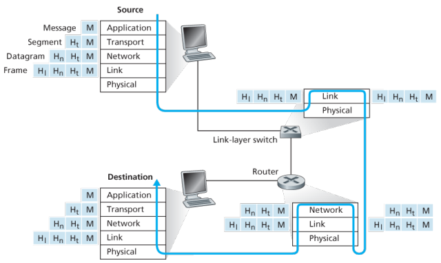
Routers and link-layer switches are both packet switches, similar to end systems, they organize their networking hardware and software into layers. But switches do not implement all of the layers in the protocol stack; they typically implement only the bottom layers.
A link-layer switches implements layers 1 and 2; routers implement layers 1 through 3, this means, for example, the Internet routers are capable of implementing the IP protocol (a layer 3) while link-layer switches are not.
At the sending host, an application-layer message is passed to the transport layer. In the simplest case, the transport layer takes the message and appends additional information so-called transport-layer header information, that will be used by the receiver-side transport layer. The application-layer message and the transport-layer header information together constitute the transport layer segment. The transport-layer segment thus encapsulates the application-layer message. The added information might include information allowing the receiver-side transport layer to deliver the message up to the appropriate application, and error-detection bits that allow the receiver to determine whether bits in the message have been changed in route.
The transport layer then passes the segment to the network layer, which adds network-layer header information such as source and destination end system addresses, creating a network-layer datagram. The datagram is then passed to the link layer, which again will add its own link-layer header information and create a link-layer frame. Thus, we see that at each layer, a packet has two types of fields: header fields and a payload field. The payload is typically a packet from the layer above.!
Network Standardization (Who is Who?)
The legal status of the world’s telephone companies varies considerably from country to country. At one extreme is the United States, which has over 2000 separate, privately owned telephone companies. At the other extreme are countries in which the national government has a complete monopoly on all communication, including the mail, telegraph, telephone, and often radio and television.
With all these different suppliers of services, there is clearly a need to provide compatibility on a worldwide scale to ensure that people (and computers) in one country can call their counterparts in another one. In 1865, representatives from many European governments met to form the predecessor to today’s ITU. Its job was to standardize international telecommunications, which in those days meant telegraphy. In 1947, ITU became an agency of the United Nations.
International standards are produced by ISO, a voluntary non-treaty organization founded in 1946. Its members are the national standards organizations of the 157 members countries. On issues of telecommunication standards, ISO and ITU-T often cooperate (ISO is a member of ITU-T) o avoid the irony of two official and mutually incompatible international standards.
NIST (National Institute of Standards and Technology) is part of the U.S. Department of Commerce. It used to be called the National Bureau of Standards. It issues standards that are mandatory for purchases made by the U.S. Government, except for those of the Department of Defense, which defines its own standards.
Another major player in the standards world is IEEE (Institute of Electrical and Electronics Engineers), the largest professional organization in the world. In addition to publishing scores of journals and running hundreds of conferences each year, IEEE has a standardization group that develops standards in the area of electrical engineering and computing.
When the ARPANET was set up, DoD created an informal committee to oversee it. In 1983, the committee was renamed the Internet Activities Board (IAB). Each of the approximately ten members of the IAB headed a task force on some issue of importance. The IAB met several times a year to discuss results and to give feedback to the DoD and NSF, which were providing most of the funding at this time. Communication was done by a series of technical reports called RFCs (Request For Comments).
By 1989, the Internet had grown so large that this highly informal style no longer worked. Many vendors by then offered TCP/IP products and did not want to change them just because ten researchers had thought of a better idea. In the summer of 1989, the IAB was reorganized again. The researchers were moved to the IRTF (Internet Research Task Force), which was made subsidiary to IAB, along with the IETF (Internet Engineering Task Force).
For Web standards, the World Wide Web Consortium (W3C) develops protocols and guidelines to facilitate the long-term growth of the Web. It is an industry consortium led by Tim Berners-Lee and set up in 1994 as the Web really begun to take off.
RFC in depth: A RFC is a publication in a series from the principal technical development and standards-setting bodies for the Internet, most prominently the IETF. An RFC is authored by individuals or groups of engineers and computer scientists in the form of a memorandum describing methods, behaviors, research, or innovations applicable to the working of the Internet and Internet-connected systems. It is submitted either for peer review or to convey new concepts, information, or occasionally, engineering humour.
The IETF adopts some of the proposal published as RFCs as Internet Standards. However, many RFCs are informational or experimental in nature and are not standards.
The RFC Editor assigns RFC a serial number. Once assigned a number and published, an RFC is never rescinded or modified; if the document requires amendments, the authors publish a revised document. Therefore, some RFCs supersede others; the superseded RFCs are said to be deprecated, obsolete, or obsoleted by the superseding RFC.
The RFC series contains three sub-series for IETF RFCs:
- BCP
- FYI
- STD
There are five streams of RFCs: IETF, IRTF, IAB, independent submission and Editorial.
Example:
- UDP RFC 768 “User Datagram Protocol”
- IPv4 RFC 791 “Internet Protocol”
- TCP RFC 793 “Transmission Control Protocol”
ICANN
The Internet Corporation for Assigned Names and Numbers (ICANN) is an American multistakeholder group and nonprofit organization responsible for coordinating the maintenance and procedures of several databases related to the namespaces and numerical spaces of the Internet, ensuring network’s stable and secure operation.
ICANN performs the actual technical maintenance work of the Central Internet Address pools and DNS root zone registries pursuant to the Internet Assigned Numbers Authority (IANA) function contract.
- Much of its work has concerned the Internet’s global Domain Name System (DNS), including policy development for internationalization of the DNS, introduction of new generic top level domains (TLDs), and the operation of root name servers.
DNS Management: ICANN oversees the global DNS, ensuring the stable and secure operation of the system. This involves managing the allocation of domain names and IP addresses, as well as the coordination of root server systems
Accreditation of Registrars: ICANN accredits domain registrars, ensuring they comply with standards and policies. Registrars act as intermediaries between individuals or organizations and the domain registration process.
IP Address Allocation: ICANN is responsible for the distribution and allocation of IP address blocks to Regional Internet Registries (RIRs), which then further allocate them to Internet Service Providers (ISPs) and organizations.
IANA Functions Oversight: ICANN oversees the Internet Assigned Numbers Authority (IANA) functions, which include the management of global IP address space, assignment of protocol parameters, and maintenance of the DNS root zone.
ICANN plays a crucial role in promoting and enhancing the security and stability of the DNS. This includes initiatives to combat cyber threats, support the implementation of DNSSEC (Domain Name System Security Extensions), and address emerging challenges.
Example: In 2013, the initial report of ICANN’s Expert Working Group has recommended that the present form of Whois, a utility that allows anyone to know who has registered a domain name on the Internet, should be abandoned.
In a long-running dispute, ICANN has so far declined to allow a Turkish company to puchase the .islam and .halal gTLDs.
Application Layer
At the core of network application development is writing programs that run on different end systems and communicate with each other over the network. For example, in the Web application there are two distinct programs that communicate with each other: the browser program running in the user’s host (desktop, laptop, tablet, smartphone, and so on); and the Web server program running in the Web server host. As another example, in a P2P file-sharing system there is a program in each host that participates in the file-sharing community.
The application architecture is designed by the application developer and dictates how the application is structured over the various end systems. In choosing the application architecture, a developer will likely draw on one of the two predominant architectural paradigms used in modern network applications: the client-server architecture or the peer-to-peer (P2P) architecture.
Client server
In a client-server architecture, there is an always-on host, called the server, which services requests from many other hosts, called clients. A classic example is the Web application for which an always-on Web server services requests from browsers running on client hosts. When a Web server receives a request for an object from a client host, it responds by sending the requested object to the client host.
Note that with the client-server architecture, clients do not directly communicate with each other; for example, in the Web application, two browsers do not directly communicate. Another characteristic of the client-server architecture is that the server has a fixed, well-known address, called an IP address.
Some of the better-known applications with a client-server architecture include the Web, FTP, Telnet and e-mail.
Often a single-server host is incapable of keeping up with all the requests from clients, for this reason, a data center, housing a large number of hosts, is often used to create a powerful virtual server. Google has 30 to 50 data centers distributed around the world which collectively handle search, You-tube, Gmail and other services.
Further:
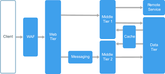
An N-tier architecture divides an application into logical layers and physical tiers. Layers are a way to separate responsibilities and manage dependencies. Each layer has a specific responsibility. A higher layer can use services in a lower layer, but not the other way around. Tiers are physically separated, running on separate machines. A tier can call to another tier directly, or use Asynchronous messaging patterns through a message queue.
Although each layer might be hosted in its own tier, that’s not required. Several layers might be hosted on the same tier. Physically separating the tiers improves scalability and resiliency, but also adds latency from the additional network communication.
A traditional three-tier application has a presentation tier, a middle tier, and a database tier. The middle tier is optional. More complex applications can have more than three tiers.
P2P
There is minimal or no reliance on dedicated servers in data centers instead the application exploits direct communication between pairs of intermittently connected host called peers. The peers are not owned by service provider, but instead are desktops and laptops controlled by users with most of the peers residing in homes, universities and offices.
Most of today’s most popular and traffic-intensive applications are based on P2P architectures, include file sharing BitTorrent, peer-assisted download acceleration, Xunlei, and Internet telephony and video conference, Skype.
Some applications have hybrid architectures, combining both client-server and P2P elements, for example many instant messaging applications, servers are used to track the IP addresses of users, but user-to-user messages are sent directly between user hosts without passing through intermediate servers.
One of the most compelling features of P2P architectures is their self-scalability. For example, in a P2P file-sharing application, although each peer generates workload by requesting files, each peer also adds service capacity to the system by distributing files to other peers.
Process communication
In jargon of OS, it is not actually programs but processes that communicate, a process can be thought of as a program that is running within an end system. When processes are running on the same end system, they can communicate with each other with IPC, using rules that are governed by end system’s operating system.
Processes on two different end systems communicate with each other by exchanging messages across the computer network, a sending process creates and sends messages into the network; a receiving process receives these messages and possibly responds by sending messages back
A network application consists of pairs of processes that send messages to each other over a network, for example, in the Web app a client browser process exchanges messages into a Web server process; in a P2P file-sharing system, a file is transferred from a process in one peer to a process in another peer.
For each pair of communicating processes, we typically label one of the two processes as the client and the other process as the server, with the web, a browser is a client process and a web server is a server process, with P2P file sharing, the peer that is downloading the file is labeled as the client, and the peer that is uploading the file is labeled as the server.
In the context of a communication session between a pair of processes, the process that initiates the communication that is, initially contacts the other process at the beginning of the session is labeled as the client, the process that waits to be contacted to begin the session is the server.
A process sends messages into, and receives messages from, the network through a software interface called a socket. A socket is the interface between the application layer and the transport layer within a host, also referred to as the Application Programming Interface (API) between the application and the network. The only control that the application developer has on the transport-layer side is
- the choice of the transport protocol and
- the ability to fix a few transport-layer parameters such as maximum buffer and maximum segment sizes
In order for a process running on one host to send packets to a process running on another host, the receiving process needs to have an address. To identify the receiving process, two pieces of information need to be specified
- the address of the host and
- an identifier that specifies the receiving process in the destination host
In the Internet, the host is identified by its IP address, which is a 32-bit quantity that we can think of as uniquely identifying the host. In addition to IP, the sending process must also identify the receiving process, more specifically, the receiving socket running the host, which is needed because in general a host could be running many network applications. A destination port number serves this purpose, popular applications have been assigned specific port numbers, a Web server is identified by port number 80, a mail server process (using the SMTP protocol) is identified by port number 25.
Transport services available to applications:
The application at the sending side pushes messages through the socket, at the other side of the socket, the transport-layer protocol has the responsibility of getting the messages to the socket of the receiving process:
- Many networks provide more than one transport-layer protocol, when you develop an application, you must choose one of the available transport-layer protocols by studying services provided by the available transport-layer protocols
- Can classify the possible services along four dimensions:
- reliable data transfer
- throughput
- timing
- security
Reliable data transfer:
- Packets can get lost within a computer network, can overflow in a buffer in a router or can be discarded by a host or router after having some of its bits corrupted
- To support data sensitive applications, transport-layer protocol provides process-to-process reliable data transfer, so the sending process can just pass its data into the socket and know with complete confidence that the data will arrive without errors at the receiving process
- Loss-tolerant applications notably multimedia applications such as conversational audio/vedio can tolerate some some amount of data loss as it results in a small glitch in the audio/video -not a crucial impairment
Throughput:
- Other sessions will be sharing the bandwidth along the network path, and because these other sessions will be coming and going, the available throughput can fluctuate with time, which lead to another natural service that a transport layer protocol could provide, namely guaranteed available throughput at some specified rate
- With such a service, the application could request a guaranteed available throughput at some specified rate of rbits/sec
- Such guaranteed throughput service would appeal to many applications, if an Internet telephony application encodes voice at 32kbps, it needs to send data into the network and have data delivered to the receiving application at this rate, such applications are bandwidth-sensitive, mainly current multimedia applications
- Meanwhile, elastic applications can make use of much, or as little, throughput as happens to be available: Electronic mail, file transfer and Web transfers
Timing:
- As with throughput guarantees, timing guarantees can come in many shapes and forms, such as that the sender pumps into the socket arrives at the receiver’s socket no more than 100 msec later, such would be appealing to interactive real-time applications, such as virtual environment, teleconferencing, and multiplayer games
Security:
- A transport protocol can provide an application with one or more security services, for ex, in the sending host, a transport protocol can encrypt all data transmitted by the sending process, and in receiving host, the transport layer protocol can decrypt the data before delivering the data to the receiving process
- Can other provide other security services in addition to confidentiality, including data integirty and end-point authentication
Transport services provided by the internet: (up-to now considered transport services that a computer network could provide in general)
The Internet makes two transport protocols available to applications, UDP and TCP, when as an application developer create a new network application for the Internet, one of the first decisions you have to make is whether to use UDP or TCP.
TCP Services: The TCP service model includes a connection-oriented service and a reliable data transfer service, when an application invokes TCP as its transport protocol, the application receives both of these services from TCP.
-
Connection-oriented service:
- TCP has the client and server exchange transport-layer control information with each other before the application-level messages begint to flow, which is so-called handshaking procedure that alterts the client and server, allowing them to prepare for an onslaught of packets
- After the handshaking, a TCP connection is said to exist between the sockets of the two processe
- The connection is a full-duplex connection in that the two processes can send messages to each other over the connection at the same time
- When the application finishes sending messages, it mus tear down the connection
-
Reliable data transfer service:
- The communicating processes can rely on TCP to deliver all data sent without error and in the proper order
- When one side of the application passes a stream of bytes into a socket, it can count on TCP to deliver the same stream of bytes to the receiving socket, with no missing or duplicate bytes
-
Congestion control?
- TCP also includes a congestion-control mechanism, a service for the general welfare of the Internet rather than for the direct benefit of the communicating process, the TCP congestion-control mechanism throttles a sending process when the network is congested between sender and receiver
-
Security?
- Neither TCP nor UDP provides any encryption -the data that the sending process passes into its socket is the same data that travels over the network to the destination process
- So, if the sending process sends a password in clear text into its socket, the cleartext password will travel over all the links between sender and receiver, potentially sniffed and discovered at an of the intervening links
- The internet community has developed an enhancement for TCP, called Secure Sockets Layer (SSL), which not only does everything that traditional TCP does but also provides critical process-to-process security services, including encryption, data integrity, and point to point authentication
UDP Services:
- UDP is no-frills, lightweight transport protocol, providing minimal services, is connection-less, so there is not handshaking before the two process start to communicate
- UDP provides an unreliable data transfer service -that is, when a process sends a message into a UDP socket, UDP provides no guarantee that the message will ever reach the receiving process, furthermore, messages that arrive at the receiving process may arrive out of order
- UDP does not include a congestion-control mechanism, so the sending side of UDP can pump data into the layer below at any rate it pleases, however, that the actual end-to-end throughput may be less than this rate due to the limited transmission capacity of intervening links or due to congestions.
Not provided services:
- Already noted that TCP provides reliable end-to-end transfer which can be easily enhanced at the application layer with SSL to provide security services, of which mention of throughput or timing guarantees are missing
- Yet internet has been hosting time-sensitive applications for many years, these applications often work fairly well because they have been designed to cope, to the greatest extent possible
- Nevertheless, clever design has its limitations when delay is excessive, or the end-to-end throughput is limited
- Today’s Internet can often provide satisfactory service to time-sensitive applications but cannot provide any timing of throughput guarantees
Applications and their services requirements:
| Applications | Data Loss | Throughput | Time-sensitive | Protocol | Transport |
|---|---|---|---|---|---|
| File trnasfer | No loss | Elastic | No | FTP | TCP |
| No | Elastic | No | SMTP | TCP | |
| Web documents | No | Elastic (kbps) | No | HTTP | TCP |
| Video conference | Loss-tolerant | Audio, video | 100 msec | SIP, RTP, prop | UDP, TCP |
| Streaming | Loss-tolerant | Audo, video | Few secs | HTTP | … |
| Games | Loss tolerant | Few kbps-10 | 100 msec | ? | |
| Messaging smart | No loss | Elastic | Yes and No | ? | |
| Many applications have chosen TCP primarily because TCP provides reliable data transfer, guaranteeing that all data will eventually get to its destination. Because telephony applications can tolerate some loss but require minimal rate to be effective, developers usually prefer to run their application over UDP, circumventing TCP congestion control and packet overheads. But because many firewalls are configured to block (most types of) UDP traffic, Internet telephony applicaitons often are designed to use TCP as a backup if UDP fails. |
Application layer protocols
An application layer protocol defines how an application’s processes, running on different end systems messages to each other, in particular, an application-layer protocol defines
- types of messages exchanged, for example, request messages and response messages.
- syntax of various message types, such as the fields in the message and how the fields are delineated.
- semantics of the fields, that is, the meaning of the formation in the fields
- rules of determining when and how a process sends messages and responds to messages
Some application-layer protocols are specified in RFCs and are therefore in the pubic domain, for ex, Web’s application-layer protocol, HTTP, is available as RFC. Many other application-layer protocol are poprietary and intentionally not available in the public domain. Important to distinguish between network applications and application-layer protocols.
DNS
Internet hosts are identified by IP addresses which is four bytes and has a rigid hierarchical structure. People rather prefer the more mnemonic host-name identifier, while routers prefer IP, in order to reconcile these preferences, need a directory service that translates hostnames to IP addresses.
The DNS is a collective term for a distributed database implemented in a hierarchy of DNS servers and an application-layer protocol that allows hosts to query the distribute database
The DNS servers are often UNIX machines running the Berkeley Internet Name Domain (BIND) software, which runs over UDP and uses port 53.
DNS is commonly employed by other application-layer protocols -including HTTP and SMTP to translate user-supplied hostnames to IP addresses. As an example, when a browser that is, HTTP client running on some user’s host requests the URL , in order for the user’s host to be able to send an HTTP request message to the Web server, the user’s host must first obtain the IP address of .
DNS provides few other important services in addition to translating hostnames to IP addresses:
-
Host alisaing: A host with a complicated hostname can have one or more alias names, for ex: a hostname such as could have, say, two aliases such as and , in this case is said to be canonical hostname. Alias hostnames, when present, are typically more mnemonic than canonical hostnames. DNS can be invoked by an application to obtain the canonical hostname for a supplied alias hostname as well as the IP address of the host.
-
Mail aliasing: The hostname of Yahoo mail server is more complicated and much less mnenomic than simply . DNS can be invoked by a mail application to obtain the canonical hostname for a supplied alias as well as the IP address of the host.
-
Load distribution: DNS is also used to perform load distribution among replicated servers such as replicated Web servers, for replicated Web servers. Busy sites, such as cnn.com , are replicated over multiple servers, with each server running on a different end system and each having a different IP address. For replicated Web servers, a set of IP addresses is thus associated with one canonical hostname. When clients make a DNS query for a name mapped to a set of addresses, the server responds with the entire set of IP addresses, but rotates the ordering of the addresses with each reply.
How DNS works for hostname-to-IP-address translation service?
When some applicaiton running in a user’s host needs to translate a hostname to an IP address, the application invokes the client side of DNS, specifying the hostname that needs to be translated. On many UNIX-based machines, is the function call that an application calls in order to perform the translation.
DNS in the user’s host then takes over, sending a query message into the network. All DNS query and replies are sent within UDP datagrams to port 53. After a delay ranging from milliseconds to seconds, DNS in the user’s host receives a DNS message that provides the desired mapping. This mapping is then passed to the invoking application.
The hierarchy of DNS servers?
A simple design for DNS would have one DNS server that contains all the mappings. Although the simplicity of this design is attractive, it is inappropriate for today’s Internet with its vast number of hosts.
A centralized database in a single DNS server simply does not scale, consequently DNS is distribued by design.
In order to deal with the issue of scale, the DNS uses a large number of servers, organized in a hierarchial fashion and distributed around the world. No single DNS server has all of the mappings for all of the hosts in the Internet. Instead the mappings are distributed across the DNS servers.
To a first approximation, there are three classes of DNS servers -root DNS servers, top-level doman (TLD) DNS, and authoritative DNS organized in a hierarchy. Suppose a DNS client wants to determine the IP address for the hostname amazon.com. The client first contacts one of the root servers, which return IP addresses for TLD servers for the top-level domain com. The client then contacts one of these TLD servers, which returns the IP address of an authorative server for amazon.com. Finally, the client contacts one of the authorative servers for amazon.com which returns the IP address for the hostname.
-
Root DNS servesr. There are over 400 root name serves scattered all over the world. These root name servers are managed by 13 different organizations. Root name servers provide the IP addresses of the TLD servers.
-
For each top-level domains, such as com, org, net, edu, gov, and all of the country top-level domain there is TLD server (or server cluster). The company Verisign Global Registry Services maintains the TLD servers for the com top-level domain. TLD servers provide IP for authoritative DNS servers.
-
Authoritative DNS servers. Every organization with publicly accessible hosts such as Web servers and mail servers on the Internet must provide publicly accessible DNS records that map the names of those hosts to IP addresses. An organization’s authoritative DNS server houses these DNS records. An organization can choose to implement its own authoritative DNS server to hold these records; alternatively, the organization can pay to have these records stored in an authorative DNS server of some service provider.
There is an another important type of DNS server called the local DNS server, does not strictly belong to the hierarchy of servers but is nevertheless central to the DNS architecture.
Each ISP - such as a residential ISP or an institutional ISP - has a local DNS server (also called a default name server). When a host connects to an ISP, the ISP provides the host with the IP addresses of one or more of its local DNS servers typically through DHCP.
A host’s local DNS server is typically close to the host, for an institutional ISP, the local DNS server may be on the same LAN as the host; for a residential ISP, it is typically separated from the host by no more than a few routers.
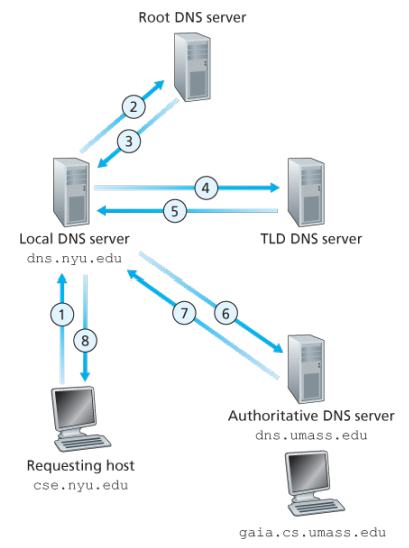
Example: Suppose the host cse.nyu.edu desires the IP address of gaia.cs.umass.edu. NYU’s local DNS server is dns.nyu.edu and that an authorative DNS server for gaia.cs.umass.edu is called dns.umass.edu 1. The host cse.nyu.edu first sends a DNS query message to its local DNS server, dns.nyu.edu containing the hostname to be translated namely gaia.cs.umass.edu 2. The local DNS server forwards the query emssage to root DNS server which takes note of the edu suffix and returns to the local DNS server a list of IP addresses for TLD servers responsible for edu 3. The local DNS server then resends the query message to one of these TLD servers which takes note of the umass.edu suffix and responds with the IP address of the authoritative DNS server for the University of Massachusetts, namely, dns.umass.edu 4. Finally query is send directly to dns.umass.edu which responds with the IP address of gaia.cs.umass.edu -Eight DNS messages were sent, assuming that the TLD server knows the authorative DNS server for the hostname, which is not always true, instead the TLD server may know only of an intermediate DNS server, which in turn knows the authorative DNS server for the hostname -(yesma bhannu parda intermediate authorative dns server hunxa rey, yei case ma ni dns.cs.umass.edu bhanni chai harek deparment ma bhako servers ko authorative huna payo, testai garera, yesko authorative arko kunai intermediate hunxa)
![[Screenshot from 2023-09-11 23-37-36.png]]
The query from the requesting host to the local DNS server is recursive, and the remaining queries are iterative.
DNS caching -DNS extensively exploits DNS caching in order to improve the delay performance and to reduce the number of DNS messages -In a query chain, when a DNS server receives a DNS reply, it can cache the mapping in its local memory -Because hosts and mappings between hostnames and IP addresses are by no means permanent, DNS servers discard cached information after a period of time often set to two days -A local DNS server can also cache the IP addresses of TLD servers, thereby allowing the local DNS server to bypass the root DNS servers in a query chain -As a result, root servers are bypassed for all but a very small fraction of DNS queries
DNS Records and Messages -The DNS servers that together implement the DNS distributed database store resource records (RRs), so each DNS reply message carries one or more resource records -A resource record is a four-tupel that contains the following fields:
(Name, Value, Type, TTL)

-TTL is the time to live of the resource record; it determines when a resource should be removed from a cache
-The meaning of Name and Value depend on Type:

1. If Type=A, then Name is a hostname and Value is the IP address for the hostname
2. If Type=Ns, then Name is a domain and Value is the hostname of an authorative DNS server that knows how to obtain the IP addresses for hosts in the domain
3. If Type=CNAME, then Value is a canoncial hostname for the alias hostname Name
4. If Type=MX, then Value is the canonical name of a mail server that has an alias hostname Name

-If a DNS server is authorative for a particular hostname, ten the DNS server will contain a Type A record for the hostname, even if it is not, may contain a Type A record in its cache
-If not authorative, then will contain a Type NS record for the domain that includes the hostname; along with it will also contain a Type A record that provides the IP address of the DNS server in the Value filed of the NS record (bhaneko agadi yo hostname ko lag authorative hosst yo ho ra tyo authorative host ko IP pani ta chaiyo ni sathi haru)

DNS Messages:
-There are only two kinds of DNS messages, both query and reply have the same format
-The first 12 bytes is the header section, which has a number of fields, first is a 16 bit number that identifies the query, which is copied into the reply message to a query, allowing the client to match received replies with sent queries
-
.....
-To send query directly from the host to some DNS server can be done with nslookup program
Inserting records into the DNS Database: -To register a domainname networkutopia.com at a registar which is a commerical entity that verifies the uniquess of the domain name, wchic enters the domain name into the DNS database, and collects a small fee from you for its services -There are many regisrars competing for customers, and the ICANN accredits the various registrars -When you register the domain name networkutopia.com with some registrar, you need to provide the registrar with the names and IP addresses of you rprimarly and secondary authorative DNS servers -Suppose the names and IP addresses are dns1.networkutopia.com, dns2.networkutopia.com, 212.2.212.1 and 212.212.212.2, for each of thse authorative DNS servers, the registrar would then make sure that a Type NS and Type A record are entered into the TLD com servers -Also need to make sure that the Type A resource record for your Web server and Type MX for your mail server are entered into your authorative DNS -Until recently, the conents of each DNS server were configured statically, for ex, from a configuration file created by a system manager -More recently, an UPDATE option has been added to the DNS protocl to allow data to be dynamically added or dleted from the database via DNS messages
The Web and HTTP
The Internet was essentially unknown outside of the academic and research communities, the Web was the first Internet application that caught the general public’s eye.
Most appealing of the Web is operating on demand, users receive what they want, when they want it, which is unlike traditional broadcast radio and television, which force users to tune in when the content provider makes the content available.
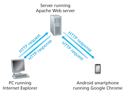
The HTTP is at the heart of the Web. HTTP is implemented in two programs: a client program and a server program, executing on different end systems, talk to each other by exchanging HTTP messages.
A web page consists of objects, an object is simply a file such as an HTML file, a JPEG image, or a video clip -that is addressable by a single URL. Most web pages consist of a base HTML file and several referenced objects. For example, if a web page consists HTML text and five JPEG, then the web page has six objects, the base HTML plus other fives images.
Each URL has two components: the hostname of the server that houses the object and the object’s path name. For example: has as a hostname and for a path name.
A segway: URIs and URLs have a shared history. Tim Berners-Lee’s proposals for hypertext implicitly introduced the idea of URL as a short string representing resource that is the target of a hyperlink. Over the next three and a half years, as the WWW core technologies of HTML, HTTP, and Web browsers developed, a need to distinguish a string that provided an address for a resource from a string that merely named a resource emerged. Although not yet formally defined, the term Uniform Resource Locator came to represent the former, and the more contentious Uniform Resource Name came to represent the latter.
Every HTTP URL conforms to the syntax of a generic URI. The URI generic syntax consists of five components organized hierarchically in order of decreasing significance from left to right:
URI = scheme ":" ["//" authority] path ["?" query] ["#" fragment]
The authority component consists of subcomponents:
authority = [userinfo "@"] host [":" port]

Back: Web browsers implement the client side of HTTP. Web servers implement the server side of HTTP, house Web objects addressable by a URL. Popular Web servers include Apache and Microsoft Information Sever.
HTTP defines how Web clients request Web pages (or objects?) from Web servers and how servers transfer Web pages to clients. When a user requests a Web page the browser sends HTTP request messages for the objects in the page to the server, the server receives the requests and responds with HTTP response messages that contain the objects.
HTTP uses TCP as its underlying transport protocol rather than running on top of UDP. The HTTP client initiates a TCP connection with the server. Once the connection is established, the browser and the server processes access TCP through their socket interfaces.
Once the client sends a message into its socket interface, the message is out of the client’s hands and is in the hands of TCP which implies that the message eventually arrives intact at the server. The server sends requested files to clients without storing any state information about the client, it completely forgets what it did earlier, HTTP is said to be a stateless protocol.
Non persistent vs persistent:
In many Internet applications, the client and server communicate for an extended period of time, with the client making a series of requests and the server responding to each of the requests. Depending on the application and on how the application is being used, the series of requests may be made back-to-back, periodically at regular intervals, or intermittently, the application developer needs to make an important decision -should each resquest/response pair be send over a separate (non-persistent) or same (persistent) TCP connection? Although HTTP uses persistent connections in its default mode, HTTP clients and servers can be configured to use non-persistent connections instead.
- Non-persistent connections:
- Steps of transferring a web page that consists of a base HTML file and 10 JPEG images and all 11 of these objects reside on the same server
http://www.someschool.edu/someDepartment/home.index. - HTTP client process initiates a TCP connection to the server
someschool.eduon port number 80, which is the default port number for HTTP, associated with the TCP connection, there will be a socket at the client and a socket at the server. - Client sends a HTTP request that includes the path name /someDeparment/home.index
- Server process receives the request message via its socket, retrieves the object from its storage, encapsulates the object in an HTTP response message, and sends to the client via its socket
- HTTP server process tells TCP to close the TCP connection but TCP doesnot actually terminate the connection until it knows for sure that the client has received the response message intact
- HTTP client receives the response message, the TCP connection terminates, the message indicates that the encapsulated object is an HTML file, the client extracts the file from the response message, examines the HTML file, and finds references to the 10 JPEG objects
- The first four steps are then repeated for each of the referenced JPEG objects.
Note that TCP connection transports exactly one request message and one response message, hence 11 TCP connections are generated. Users can configure modern browsers to control the degree of parallelism, in their default modes, most browsers open 5 to 10 parallel TCP connections and each of these connections handles one request-response transaction.
To initiate a TCP connection involves three way handshake, the client sends a small TCP segment to the sever, the server acknowledges and responds with a small TCP segment, and finally, the client acknowledges back to the server with the HTTP request message. Thus, roughly, the total response time is two round-trip times plus the transmission time at the server of the HTML file.
- Persistent connections:
- For each of non-persistent connections, TCP buffers must be allocated and TCP variables must be kept in both the client and server, can be a significant burden on a Web server, which may be serving requests from hundreds of different clients
- Each object suffers a delivery delay of two RTTs
- With HTTP 1.1 persistent connections, the server leaves the TCP connection open after sending a response, subsequent requests and responses between the same client and server can be sent over the same connection
- Multiple web pages residing on the same server can be sent from the server to the same client over a single persistent TCP connection, can be made back to back without waiting for replies to pending requests (pipelining)
- Typically HTTP server closes a connection when it isnt used for a certain time (a configurable timeout interval)
- HTTP/2 allows multiple requests and replies to be interleaved in the same connection, and a mechanism for priotizing HTTP message requests and replies within this connection
HTTP Message format:
There are two types of HTTP messages, request messages and response messages
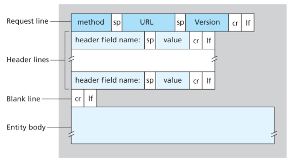
General format of HTTP request message:
Properties
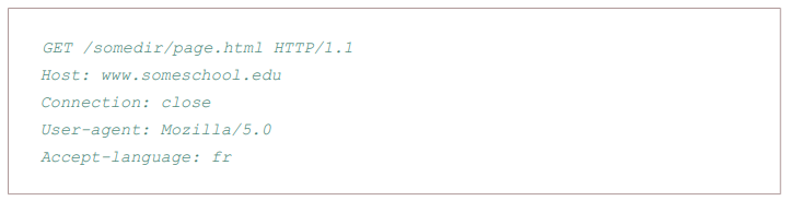
- Message is written in ordinary ASCII text.
- Message consists of five lines, each followed by a carriage return and a line feed, the last line is followed by an additional carriage return and line feed
- Although this particular has five lines, a request message can have many more lines or as few as one line
- The first line of an HTTP request is the request line; subsequents are header lines
- The request line has three fields: the method field, the URL field, and the HTTP version field
- The method field can take on several different values, including GET, POST, HEAD, PUT, and DELETE
- Great majority of HTTP request message use the GET method, which is used when the browser requests an object, with the requested object identified in the URL field
- The header line Host specifies the host on which the object resides, which seems unnecessary, as there is already a TCP connection in place to the host but the information provided by the host header is required by Web proxy caches.
- By providing Connection header line, the browser is telling the server that it does not want to bother with persistent connections; it wants the server to close the connection after sending the requested object.
- The User-agent: header specifies the user agent, that is, browser type that is making the request to the server which is useful because the server can actually send different versions of same object to different types of user agents
- The Accept-language indicates the version of the object that the user prefers
- The entity body is empty with the GET method, but is used with the POST method
- An HTTP client often uses the POST method when the users fills out a form -for example, when a user provides search words to a search engine, with a POST message, the user is still requesting a Web page from the server, but the specific contents of the Web page depends on what the user entered into the form fields
- A request generated with a form does not necessarily use the POST method, instead HTML forms often use the GET method and include the inputted data in the form fields in the requested URL, if a form uses the GET method, has a field with input ‘monkey’, then the URL will have structure …/search?monkeys
- HEAD method is similar to GET method, when a server requests with the HEAD method, it responds with an HTTP message but leaves out the requested object, often used for debugging
- The PUT method is often used in conjuction with Web publishing tools, allows a user to upload an object to a specific directory on a Web server, used by applications that need to upload objects to Web servers
- The DELETE method allows a user, or an application to delete an object on a Web server
Typical HTTP response message:
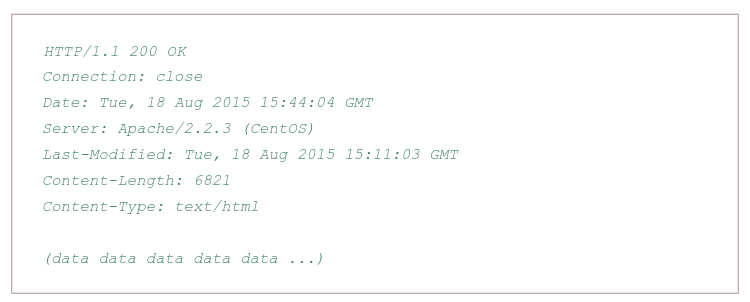
Properties:
- Has three sections: an initial status line, six header lines, and then the entity body, which is the meat of the message which contains the requested object iself
- The status line has three fields: the protocol version field, a status code, and a corresponding status message, and a corresponding status messagse
- The status code and associated phrase indicate result of the request, some common status codes and associated phrases:
- 200 OK: Request succeeded and the information is returned in the response
- 301 Moved Permanently: Requested object has been permanently moved; the new URL is specified in Location: header of the response message, client software will automatically retrieve the new URL
- 400 Bad Request: Generic error code indicating that the request could be understood by the server
- 404 Not Found: Requested document does not exist on this server
- 505 HTTP Version Not Supported
- The server uses the Connection: close header line to tell the client that it is going to close the TCP connection after sending the message
- The Date: header line indicates the time and date when the HTTP response was created and sent by the server, which is not when the object was created or last modified
- The Server indicates that the message was generated by an Apache Web server; it is analogous to User-agent header in the HTTP request message
- The Last-Modified is critical for object caching, both in the local client and in network cache servers also known as proxy servers
- The Content-Length: header indicates the number of bytes in the object being sent
- The Content-Type: header line indicates that the object in the entity body is HTML text which is officially indicated by the Content-Type: header and not by the file extension
Real and web browser packets: First telnet into your favourite web server, then type in a one-line request message for some object that is housed on the server
telnet pcampus.edu.np 80
GET /index.html HTTP/2.0
Host: pcampus.edu.np
After carriage return twice, opens a TCP connection to port 80 of the host gais.cs.umass.edu and then sends the HTTP request message
- The HTTP specification defines many, many more header lines that can be inserted by browsers, Web servers, and network cache servers
- A web browser will generate header lines as a function of the browser type and version, the user configuration of the browser, and whether the browser currently has a cached, but possibly out-of-date version of the object, web servers behave similarly
User-server interaction/ cookies: As HTTP server is stateless, simplifies server design and has permitted engineers to develop high-performance Web servers that can handle thousands of simultaneous TCP connections. Often desirable for a site to identify users, for these purposes, HTTP uses cookies, which allow sites to keep track of users
Cooking technology has four components:
- a cookie header line in the HTTP response message
- a cookie header line in the HTTP request message
- a cookie file kept on the user’s end system and managed by the user’s browser
- a back-end database at the Web site
How cookie works?
- When the request comes into the Amazon web server for the first time, their server creates a unique ID and creates an entry in its backend database that is indexed by the ID
- The server then responds back with HTTP response including a Set-cookie header which includes the ID
- When browser receives the HTTP response message, it sees the Set-cookie header, then the browser appends a line to the special cookie file which includes the hostname of the server and the ID in the Set-cookie header
- As the browser continues to request a Web page for the site, puts a cookie header line that includes the ID in the HTTP request. faIf registered providing full name, email, then Web server can include this information in database, thereby associating personal information with identification number
Web caching
A proxy server is a network entity that satisfies HTTP requests on the behalf of an origin Web server, which has its own disk storage and keeps copies of recently requested objects in this storage.
A web browser can be configured so that all of the user’s HTTP requests are first directed to the Web cache.
- The browser establishes a TCP connection to the Web cache and sends an HTTP request for the object to the Web cache.
- The Web cache checks to see if it has a copy of the object stored locally, if it does, returns the object within an HTTP response message to the client browser
- If does not, the Web cache opens a TCP connection to the server, then sends an HTTP request for the object into the cache-to-server TCP connection.
Typically is purchase and installed by an ISP
Can substantially reduce the response time for a client request, particularly if the bottleneck bandwidth between the client and the origin server is much less than the bottleneck bandwidth between the client and the cache
Can substantially reduce traffic on an institution’s access link to the Internet
The Content Distribution Networks install many geographically distributed caches throughout the internet, thereby localizing much of the traffic
The Conditional GET:
- Caching can reduce user-perceived response times, introduces a new problem - the copy of an object residing may be stale, may have been modified since the copy was cached at the client.
- HTTP has a mechanism that allows a cache to verify that its objects are up to date called the conditional GET
- So the cache now also stores the last-modified date along with the object, then if another browser requests the same object via the cache, and the object is still in the cache, it performs an up-to-date check by issuing a conditional GET, specifically it sends:
GET /fruit/kiwi.gif HTTP/1.1
Host: www.exotiquecuisine.com
If-modified-since: Wed, 9 Sep 2015 09:23:24
The conditional GET is telling the server to send the object only if the object has been modified since the specified date, if has not been modified then the Web server sends a response message to the cache with empty entity body.
Web App (now after understanding http technology, understand how to build a web app, what the fuck is html?)
(dont know where to put this so i am putting it here:)
Load balancing
Load balancing is the practice of distributing computational workloads between two or more computers. On the Internet, load balancing is often employed to divide network traffic among several servers. This reduces the strain on each server and makes the servers more efficient, speeding up performance and reducing latency. Load balancing is essential for most Internet applications to function properly.
Round robin DNS: is a technique of load distribution, load balancing, or fault tolerance provisioning multiple, redundant IP service hosts, e.g. Web server, FTP servers, by managing the DNS responses to address requests from client computers according to an appropriate statistical model. In its simplest implementation, round-robin DNS works by responding to DNS requests not only with a single potential IP address, but with a list of potential IP addresses corresponding to several servers that host identical services.
-
Although easy to implement, round-robin DNS has a number of drawbacks, such as those arising from record caching in the DNS hierarchy itself, as well as client-side address caching and reuse, the combination of which can be difficult to manage.
-
May not be best choice for load balancing on its own, since it merely alternates the order of the address records each time a name server is queried. Because it does not take transaction time, server load, and network congestion into consideration, it works best for services with a large number of uniformly distributed connections to servers of equivalent capacity.
Internet Cache Protocol (ICP): is a UDP based protocol for coordinating web caches. Its purpose is to find out the most appropriate location to retrieve a requested object in the situation where multiple caches are in use at a single site. T to retrieve a requested object in the situation where multiple caches are in use at a single
Operation:
- Hierarchically, a queried cache can either be a parent or a sibling
- Parents usually sit closer to the internet connection than the child. If a child cache cannot find an object, the query usually will be sent to the parent cache, which will fetch, cache, and pass on the request. Siblings are caches of equal hierarchical status, whose purpose is to distribute the load amongst the siblings.
- When a request comes into one cache in a cluster of siblings, ICP is used to query the siblings for the object being requested. If the sibling has the object, it will usually be transferred from there, instead of being queried from the original server. This is often called a “near miss” — the object is not found in the cache (a “miss”) but is loaded from a nearby cache, instead of from a remote server.
Bad: Generates extra network traffic, more proxy servers = more querying, caches become redundant
Cache Array Routing Protocol: The CARP is used in load balancing HTTP requests across multiple proxy cache servers. It works by generating a hash for each URL requested. A different hash is generated for each URL and by splitting the hash namespace into equal parts (or unqual parts if uneven load is intended) the overall number of requests can be distributed to multiple servers.
With the CARP, an array containing multiple servers can act as a single logical cache.
- Because CARP determines the best request resolution path, there is no query messaging between proxy servers in an array, as is found with conventional Internet Cache Protocol (ICP) networks. By doing this, CARP avoids the heavier query congestion that normally occurs with a greater number of servers.
- CARP eliminates the duplication of content that otherwise occurs on an array of proxy servers. With an ICP network, an array of five proxy servers can rapidly evolve into duplicate caches of the most frequently requested objects. The hash-based routing of CARP keeps this from happening by allowing all five Forefront TMG servers to exist as a single logical cache. The result is a faster response to queries and a far more efficient use of server resources.
- CARP has positive scalability. Due to its hash-based routing and its resultant independence from peer-to-peer pinging, CARP becomes faster and more efficient as more proxy servers are added. ICP arrays must conduct queries to determine the location of cached information. This is an inefficient process that generates extraneous network traffic. ICP arrays have negative scalability: the more servers added to the array, the more querying required between servers to determine location.
HTTP/2
HTTP/2 is a major revision of the HTTP network protocol by WWW. It was derived from the earlier experimental SPDY protocol, originally developed by Google.
The working group charter mentions several goals and issues of concern:
- Create a negotiation mechanism that allows clients and servers to elect to use HTTP/1.1, 2.0, or potentially other non-HTTP protocols
- Maintain high-level compatibility with HTTP/1.1
- Decrease latency to improve page load speed in web browsers by considering:
- data compression of HTTP headers
- HTTP/2 Server Push
- prioritization of requests
- multiplexing multiple requests over a single TCP connection (fixing the HTTP-transaction-level head-of-line blocking problem in HTTP 1.x even when HTTP pipelining is used). HOL blocking in computer networks is a performance limiting phenomenon that occurs when a line of packets is held up in a queue by a first packet.
HTTP/3
HTTP/3 is a third major version of HTTP used to exchange information on the WWW, complemending widely-deployed HTTP/1.1 and HTTP/2. Unlike previous versions which relied on well-established TCP, HTTP/3 uses QUIC, a multiplexed transport protocol built on UDP.
HTTP/3 uses similar semantics compared to earlier revisions of the protocol, including the same request methods, status codes, and message fields, but encodes and maintains session state differently. However, partially due to the protocol’s adoption of QUIC, HTTP/3 has lower latency and loads more quickly in real-world usage when compared with previous versions: in some cases over 3× faster than with HTTP/1.1
QUIC allows for a quicker connection establishment compared to traditional TCP handshakes.
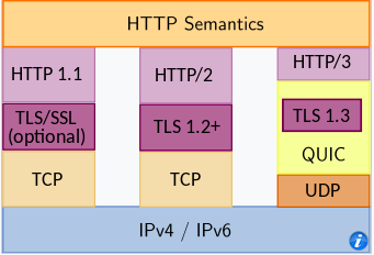
FTP
In a typical FTP session, the user is sitting in front of one host (the local host) and wants to transfer files to or from a remote host. In order for the user to access the remote account, the user must provide a user identification and a password.
After providing this authorization information, the user can transfer files from the local file system to the remote file system and vice versa.
The user interacts with FTP through an FTP user agent. The user first provides the hostname of the remote host, causing the FTP client process in the local host to establish a TCP connection with the FTP server process in the remote host. The user then provides the user identification and password, which are sent over the TCP connection as part of FTP commands.
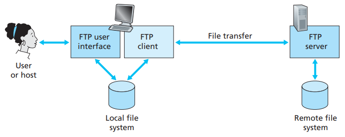 Once the server has authorized the user, the user copies one or more files stored in the local file system into the remote file system (or vice versa).
HTTP and FTP are both file transfer protocols and have many common characteristics; for example, they both run on top of TCP. However, the two application-layer protocols have some important differences. The most striking difference is that FTP uses two parallel TCP connections to transfer a file, a control connection and a data connection.
The control connection is used for sending control information between the two hosts—information such as user identification, password, commands to change remote directory, and commands to “put” and “get” files.
The data connection is used to actually send a file. Because FTP uses a separate control connection, FTP is said to send its control information out-of-band.
- When a user starts an FTP session with a remote host, the client side of FTP (user) first initiates a control TCP connection with the server side (remote host) on server port number 21.
- The client side of FTP sends the user identification and password over this control connection. The client side of FTP also sends, over the control connection, commands to change the remote directory.
- When the server side receives a command for a file transfer over the control connection (either to, or from, the remote host), the server side initiates a TCP data connection to the client side.
- FTP sends exactly one file over the data connection and then closes the data connection. If, during the same session, the user wants to transfer another file, FTP opens another data connection.
Throughout a session, the FTP server must maintain state about the user. In particular, the server must associate the control connection with a specific user account, and the server must keep track of the user’s current directory as the user wanders about the remote directory tree.
The commands, from client to server, and replies, from server to client, are sent across the control connection in 7-bit ASCII format. Thus, like HTTP commands, FTP commands are readable by people. In order to delineate successive commands, a carriage return and line feed end each command. Each command consists of four uppercase ASCII characters, some with optional arguments. Some of the more common commands are given below:
- USER username
- PASS password
- LIST:
- RETR filename
- STOR filename
There is typically a one-to-one correspondance between the command that user issues and the FTP command sent across the control connection. Each command is followed by a reply, sent from server to client. The replies are three-digit numbers, with an optional message following the number.
Electronic mail
Email is an asynchronous communication medium -people send and read messages when it is convenient for them, without having to coordinate with other people’s schedules. In contrast with postal mail, electronic mail is fast, easy to distribute, and inexpensive.
The high-level view of Internet mail system has three major components: user agents, mail servers, and the Simple Mail Transfer Protocol (SMTP).
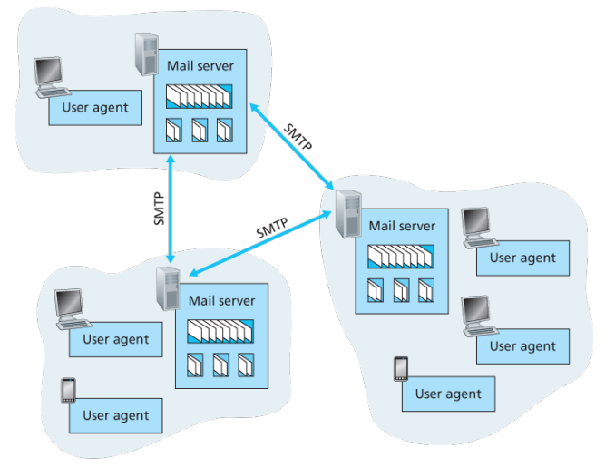
User agents allow users to read, reply to, forward, save, and compose messages such as Outlook and Apple Mail.
When Alice is finished composing her message, her user agent sends the message to her mail server, where the message is placed in the mail server’s outgoing message queue. When Bob wants to read a message, his user agent retrieves the message from his mailbox in his mail server
Each recipient such as Bob, has a mailbox located in one of the mail server. A typical message starts its journey in the sender’s user agent, travels to the sender’s mail server, and travels to the recipient’s mail server, where it is deposited in the recipient’s mailbox.
When Bob wants to access his mailbox, the mail server containing his mailbox authenticates Bob with usernames and passwords. Alice’s mail server must also deal with failures in Bob’s mail server. If Alice’s server cannot deliver mail to Bob’s server, Alice’s server holds the message in a message queue and attempts to transfer the message later.
Reattempts are often done every 30 minutes or so; if there is no success after several days, the server removes the message and notifies the sender with an e-mail message.
SMTP is the principal application-layer protocol which uses reliable service of TCP to transfer mail from the server’s mail server to recipient’s mail server.
SMTP is much older than HTTP. SMTP has two sides: a client side, which executes on the sender’s mail server, and a server side, which executes on the recipient’s mail server.
Although SMTP has numerous wonderful qualities, as evidenced by its ubiquity in the Internet, it is nevertheless a legacy technology that possesses certain archaic characteristics. For example, it restricts the body not just the headers of all mail messages to simple 7-bit ASCII. While HTTP does not require multimedia data to be ASCII encoded before transfer.
It is important to observe that SMTP does not normally use intermediate mail servers for sending mail, even when the two mail servers are located at opposite ends of the world. In particular, even if one server is down, the message remains in the sender’s mail server and waits for a new attempt - the message does not get placed in some intermediate mail server.
Process:
First the client SMTP running on the sending mail server host has TCP establish a connection to port 25 at server SMTP running on the receiving mail server host, if the server is down, the client tries again later >Once this connection is established, the server and client perform some application-layer handshaking, during this SMTP handshaking, he SMTP client indicates the email of the sender, the person who generated the message and email address of the recipient >SMTP can count on reliable data transfer of TCP to get the message to server without errors, the client then repeats this process over the same TCP connection if it has other messages to send to the server; otherwise, it instructs TCP to close the connection
Example: An transcript of messages exchanged between an SMTP client (C) and an SMTP server (S), the hostname of the client is crepes.fr and the hostname of the server is hamburger.edu, the following ASCII text lines prefaced with C: are exactly the lines the client sends into its TCP socket, and the ASCII text lines prefaced with S: are exactly the lines the server sends into its TCP socket:

S: 220 hamburger.edu
C: HELO crepes.fr
S: 250 Hello crepes.fr, pleased to meet you
C: MAIL FROM: <alice@crepes.fr>
S: 250 alice@crepes.fr ... Sender ok
C: RCPT TO: <bob@hamburger.edu>
S: 250 bob@hamburger.edu .. Receipt ok
C: DATA
S: 354 Enter mail, end with "." on a line by itself
C: Do you like ketchup?
C: How about pickles?
C: .
S: 250 Message accepted for delivery
C: QUIT
S: 221 hamburger.edu closing connection

-The client sends a message ("Do you like ketchup? How about pickles?") from maile server crepes.fr to mail server hamburger.edu
-As part, client issued five commands: HELO, MAIL, FROM, RCPT, TO, DATA, and QUIT
-Here SMTP uses persistent conenctions: if the sending mail server has several messages to send to the same receiving mail server, it can send all of the messages over the same TCP connection
-For each message, the client begins the process with a new MAIL FROM: crepes.fr, designates the end of the message with an isolated period, and issues QUIT only after all messages have been sent out


Comparison with HTTP:
-When transfering the files, both persistent HTTP and SMTP use persistent conenctions
-First HTTP is mainly a pull protocol -someone loads information on a Web server and users use HTTP to pull the information from the server at their convenience, in particular, the TCP connection is initiated by the machine that wants to receive the file
-On the other hand, SMTP is primarily a push protocol - the sending mail server pushes the file to the receiving mail server
-A second difference is that SMTP requires each message, including the body of each message to be in 7-bit ASCII format, if does not or contains binary then the message has tob e encoded into 7-bit ASCII
-HTTP encapsulates each object in its own HTTP response message, SMTP places all of the message's objects into one message


-When an email message is sent from one person to another, a header containing peripheral information precedes the body of the message itslef, is contained in a series of header lines
-As with HTTP, each header line contains readable text, consisting of a keyword followed by a colon followed by a value
-The header lines and the body of the message are separated by a blank line CRLF
-Every header must have a From: header line and and a To: header line; a header may incldue a Subject: header line as well as other optional header lines
-Those header lines are different from SMTP commands, where were part of the SMTP handshaking protocol; the header lines here are part of the mail message itself
-After the message header, a blank line follows; then the message body in ASCII follows
Mail Access Protocols:
Once SMTP delivers the message from Alice’s mail server to Bob’s mail server, the message is placed in Bob’s mailbox. Up until early, Bob reads his mail by logging onto the server host and then executing a mail reader that runs on that host.
But today, mail access uses a client-server architecture -the typical user reads e-mail with a client that executes on the user’s end system. By executing a mail client on a local PC, users enjoy a rich set of features, including the ability to view multimedia messages and attachments.
To send email messages from Alice’s user agent to Alice’s mail server, can simply be done with SMTP indeed SMTP has been designed for pushing email from one host to another.
Alice’s user agent uses SMTP to push the email message into her mail server, then Alice’s mail server uses SMTP as an SMTP client to relay the email message to Bob’s server.
But there is still one missing piece to the puzzle? How does a recipeint like Bob, running a user agent on his local PC, obtain his messages, which are sitting in a mail server within Bob’s ISP? The Bob’s user agent cant use SMTP to obtain messages because obtaining the messages is a pull operation, whereas SMTP is a push protocol.
The puzzle is completed by introducing a special access protocol that transfers messages from Bob’s mail server to his local PC including POP3, IMAP, and HTTP.
POP3
POP3 is an extremely simple mail access protocol which is short and quite readable. Because the protocol is simple, it functionality is rather limited. POP3 begins when the user agent (the client) opens a TCP connection to the mail server on port 110.
With the TCP connection established, POP3 progresses through three phases: authorization, transaction, and update.
- During the first phase, authorization, the user agent sends a username and a password in the clear to authenticate the user.
- During the second phase, transaction, the user agent retrieves messages; also during which, the user agent can mark messages for deletion, remove deletion marks, and obtain mail statistics. A user agent using POP3 can often be configured to download an delete or download and keep. In the download-and-delete, mode the user will issue the list, retr and dele commands.
- The third phase, update, occurs after the client has issued the quit command, ending the POP3 session; at this time, the mail server deletes the messages that were marked for deletion.
In a POP3 transaction, the user agent issues commands, and the server responds to each command with a reply, are two possible responses: +OK (sometimes followed by server-to-client data), used by the server to indicate that ther previous command was fine; and -ERR, used by the server to indicate that something was wrong with the previous command.
A problem with this download-and-delete mode is that the recipient, Bob, may be nomadic and may want to access his mail messages from multiple machines, for example, his office PC, home PC. The download-and-delete mode partitions Bob’s mail messages over these three machines; in particular, if Bob first reads a message on his office PC, he will not be able to reread the message from his portable at home later in the evening. In the download-and-keep mode, the user agent leaves the messages on the mail server after downloading them. In this case, Bob can reread messages from different machines; he can access a message from work and access it again later in the week from home.
IMAP
POP3 does not provide any means for a user to create remote folders and assign messages to folders. To solve this and other problems, the IMAP, protocol was invented. Like POP3, IMAP is an mail access protocol. It has many more features than POP3 and is also significantly more complex to implement.
An IMAP server will associate each message wih a folder; when a message first arrives at the server, it is first associated with the recipent’s INBOX folder. The recipient can then move message into a new user-created folder, read the message, delete and so on.
The IMAP protocol provides commands to commands that permit a users obtain components of messages, for ex: a user agent can obtain just the message header of a message or just one part of a multipart MINE message. This feature is useful when there is a low-bandwidth connection between the user agent and its mail server.
Web-based email:
-With web based emails, the user cagent communicates with its remote mailbox via HTTP
-When a sender, such as Alice, wants to send an email message, the email message is sent from her browser to her mail server over HTTP rather than over SMTP
-Alice's mail server, however, still sends messages to, and receives messages from, other mails ervers using SMTP
(DNS)
Peer-to-peer file distribution
A very natural P2P application is distributing a large file from a single server to a large number of hosts called peers
In client-server file distribution, the server must send a copy of the file to each of the peers—placing an enormous burden on the server and consuming a large amount of server bandwidth
Each peer can redistribute any portion of the file it has received to any other peers, thereby assisting the server in the distribution process, such as BitTorrent protocol
Comparison:
>Upload rate of the server's access link: us
>Upload rate of ith peer's access link: ui
>Download rate of the ith peer's access link: di
>Size of the file to be distributed: F
>Number of peers that want to obtain a copy of the file: N

-Server must transmit NF bits so time to distribute must be at least NF/us
-The peer with the lowest download rate cannot obtain all F bits of the file in less than F/dmin seconds

Thus, Dcs >= min{NF/us, F/dmin}
The distribution increases linearly with number of peers N
At the beginning, only the server has the file, to get the file into the community of peers, the server must send each bit of the file at least once into its access link, thus minimum time is at least F/us
The peer with lowest download rate cannot obtain F bits of the file in lesss than F/dmin seconds, thus minimum distrbution time is at least F/dmin -Finally the upload capacity of the system as a whole is equal to the upload rate of the server plus the upload rates of each of the individual peers that is, utotal = us+u1+…+uN -The system must deliver F bits to each of the N peers, thus delivering a total of NF bits cannot be done faster than utotal so min is NF/(us+u1+…+uN)
BitTorrent:
The collection of all peers participating in the distribution of a particular file is called a torrent
Peers in a torrent download equal-size chunks of the file from one another, with a typical chunk size of 246 KB
When a peer first joins a torrent, it has no chunks, over time it accumulates more and more chunks, while it download chunks it also upload chunks to other peers
Once a peer has acquired the entire file, it may leave the torrent, or remain in the torrent and continue to upload chunks to other peers
Each torrent has an infrastructure node called a tracker
When a peer joins a torrent, it registers itself with the tracker and periodcailly informs the tracker that it is still in the torrent
When a new peer, Alice, joins the torrent, the tracker randomly selects a subset of peers, say 50 from the participating peers, and sends the IP addresses of these 50 peers to Alice
Alice attempts to establish a TCP connections with all peers on thist list,
As time evolves, some of these peers may leave and other peers (outside the initial 50) may attempt to establish TCP connections with Alice.
Periodically, Alice will ask each of her neighboring peers over the TCP connections for the list of the chunks they have (list ho hai not actual chunks)
If Alice has L different neighbors, she will obtain L lists of chunks, with knowledge, Alice will issue requests for chunks she currently does not have
At any given instant of time, Alice will have a subset of chunks and will known which chunks her neighbors have
With this information, Alice will have two important decisions to make, first, which chunks should she request first from her neighbors? and second, to which of her nieghbors should she send requested chunks?
1. Alice uses a technique called rarest first, with the idea to detemine from among the chunks she does not have, the chunks that are the rarest among her neighbors ie the chunks that have the fewest repeated copies among her neighbors
2. To determine which requests she responds to, BitTorrent uses a clever trading algorithm,
	-Basic idea that Alice gives priority to the neighbors that are currently supplying her data at the highest rate
	-Alice continually measure the rate at which she receives bits and determines the four peers that are feeding her bits at the highest rate, then reciprocates by sending chunks to these same four peers.
	-Every 10 seconds, seh recalculates the rates and possibly modifies the set of four peers, they are said to be unchoked
	-Importantly, every 30 seconds, she also picks one additional neighbor at random and sends it chunks, is said to be optimistically unchoked, if the rate at which Bob sends data to Alice is high enough, Bob could then be one of the new trding partner
	-Effect is that peers capable of uplaoding at compatible rates tend to find each other
	-All other nieghboring peers besides these five peers are choked that is, they do not receive any chunks from Alice
Content Delivery
Sine the Web grew up, however, the Internet has become more about content than communication. Many people use the Web to find information, and there is tremendous amount of peer-to-peer file sharing that is driven by access to movies, music, and programs. The switch to content has been so pronounced that the majority of Internet bandwidth is now used to deliver stored videos.
Voice Over Internet Protocol
Video streaming and content distribution networks
From a networking perspective, the most salient characteristic of video is its high bit rate, ranges from 100 kbps or low-quality video to over 3 Mbps for streaming high-definition movies; 4K streaming envisions a bitrate of more than 10Mbps
In HTTP streaming, the video is simply stored at an HTTP server as an ordinary file with a specific URL, when a user wants to see the video, the client establies a TCP connection with the server and issues an HTTP GET request.
On the client side, the bytes are collected in a client application buffer, once the number of bytes in this buffer exceeds a predetermined threshold, the client application begins playback, the streaming video application periodically grabs video games from the client application buffer, decompresses and displays on the screen.
Major shortcoming is that all clients receive the same encoding of the video, despite the large variations in the amount of bandwidth available to a client, both across different clients and also over time for the same client.
In Dynamic Adaptive Streaming over HTTP, the video is encoded into several different versions, with each version having a different bit rate, and correspondingly, a different quality. The client dynamically requests chunks of video segments of a few seconds in length, when the amount of available bandwidth is high, the client naturally selects chunks from a high-rate version; and when the available bandwidth is low, it naturally selects from a low-rate version.
Content distribution networks:
The most straightforward approach to provide video streaming is to build massive data center, store all of the videos in it and stream videos directly from the data center to clients worldwide
Three major problems with this approach:
- If the client is far from data center, server-to-client packets will cross many communication links and likely pass through many ISPs, with some of the ISPs possibly located on different continents, if one of these links provides a throughput that is less than the video consumption rate, the end-to-end throughput will also be below consumption rate, resulting in freezing.
- Popular video will likely be sent many times over the same communication links, not only wastes bandwidth, but video company will be paying its provider ISP for sending the same bytes into the Internet over and over again
- Data center as a single point of failure
Almost all video-streaming companies make use of CDNs, that manages servers in multiple geographically distributed locations, stores copies of the videos and other types of Web content, including documents, images and audio in its severs and attempts to direct each user request to a CDN location that will provide the best user experience.
The CDN may be a private CDN, that is, owned by the content provider itself; for example, Google’s CDN distributes Youtube videos and other types of content.
Once its clusters are in place, the CDN replicates content across its clusters, may not want to place a copy of every video in each cluster, since some videos are rarely viewed or are only popular in some countries. Many CDNs do not push videos to their clusters but instead use a simple pull strategy; if a client requests a video from a cluster that is not storing the video, then the cluster retrieves the video from the central or from another cluster and stores a copy locally while streaming the video to the client at the same time
CDN Operation:
When browswer requests a video, the CDN must intercept the request so that
- it can determine a suitable CDN server cluster for that client at that time, and
- redirect the client’s request to a server in that cluster
Most CDNs take advantage of DNS to intercept and redirect requests
Example: NetCinema employs third party CDN compandy kingCDN to distribute its videos to its customers:
1. The user vists the Web page at NetCinema
2. When the user clicks on the link, the user's hsot sends a DNS query for video.netcinema.com
3. The user's Local DNS serer relays the query to an authorative DNS server for NetCinema which observes the string video in the hostsname
3. Hands over the DNS query to KingCDN instead of returning an IP address, the NetCinema authorative DNS server returns to the LDNS a hostname in KingCDN's domain for example, a10003.kingcdn.com
4. From this point on, the DNS query enters into KingCDN's private DNS infrastrucutre, the user's LDNS then sends a second query now for a1003.kingcdn.com, and KingCDN's DNS eventually returns the IP address of a KingCDN content server to the LDNS
5. THe LDNS forwards the IP address of the conente-serving CND node to ithe user's host
6. Once the client receives the IP address for a KingCDN content server, it establiehes direct TCP connection

.....(wtf is that)
Socket programming:
-A typical network application consists of a pair of programs -a client program and a server pgoram -residing in two different end systems
-When these two programs are executed, a client process and a server process are created, and these processes communicate with each other by reading from, and writing, to sockets

UDP programming:
-The application developer has control of everything on the application-layer ide of the socket; however it has little control of the transport-layer side
-Before the sending process can push a packet of data out the socket door, when using UDP, it must first attach a destination address to the packet, after the packet passes through the sender's socket, the Internet will use this destination address to route the packcet through the Internet to the socket in the receiving process
-When the packet arrives at the receiving socket, the receiving process will retrieve the packet through the socket, and then inspect the packet's contents and take appropriate action

>The destination host's IP address is part of the destination address, by including it in the packet, the routers in the Internet will be able to route the packet through the Internet to the destination host
>But because a host may e running many network application processes, each with one or more sockets, it is also necessary to identify the particular socket in the destination host, when a socket is created, an identifier, called a port number, is assigned to it
>Moreover, the sender's source address -consisting of the IP address of the source host and the port number of the source socket -are also attached to the packet, however attaching the source address to thep akcet is typically not doen by the UDP application code; instead automically done by underlying OS

-In order for the server to be able to receive and reply to the client's messsage, it must be ready and running ie, must be running as a process before the client sends it message

(CODE IN CODE)


[Some other protocols from the sir's slides]
-A framework for managing devices in an internet using the TCP/IP protocol suit - used for set of management applications: Data analysis and Fault recovery
-Some softwares:
	>Multi Router Traffic Grapher: free software for monitoring and measuring the traffic load on network links
	>Uses the SNMP to send requests with two object identifies to a device