WSC Architecture
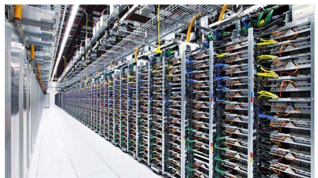
- Warehouse-scale computers (WSCs) integrate 50,000 to 100,000 compute servers and storage blocks interconnected via a hierarchical network.
- Hardware is physically structured in racks containing IT equipment, AC to DC power converters, and backup batteries.
- Racks measure 19 inches wide by 48 inches deep, with heights ranging from 70 to 84 inches; vertical space is measured in rack units where inches or cm.
- The quantity of servers per rack is strictly bounded by available power (typically 10 to 30 KW per rack), cooling limits, airflow constraints, and available network fabric bandwidth.
WSC Compute
WSCs are more homogeneous than traditional enterprise data centers, but they still deploy multiple server configurations to match hardware capability and cost to major workload classes. Racks may mix server types or remain partially populated when power, cooling, airflow, or network limits are reached. Since hardware is replaced gradually, a WSC contains multiple server and rack generations over its lifetime.
- Standard Server Configurations:
- Meta’s 2017 WSC design used seven server types, ranging from single-socket compute enclosures to analytics, service, cold-storage, disaggregated Flash, and storage-heavy servers.
- 1RU 2-socket servers balance compute and memory capacity for general-purpose applications and VM slicing. They are cost-effective because fixed costs such as the enclosure, motherboard, fans, and NIC are amortized across two CPU sockets.
- OCP-style 1RU servers may include two high-core-count CPUs, large DDR memory capacity, NVMe/SAS/SATA drives, M.2 NVMe drives, and PCIe expansion for NICs or storage enclosures. In WSC deployments, rack-level power modules commonly provide DC power directly.
- Multi-Node Servers:
- Multi-node designs such as Meta Yosemite pack multiple 1-socket server blades into a shared chassis to increase density and reduce per-server overhead.
- Yosemite v3 uses a 3RU chassis with 3 vertical sleds and 4 blades per sled; a fully populated OCP Open Rack v2 can fit 8 chassis, or 96 1-socket servers.
- A base Yosemite sled has four 1-socket servers plus a shared baseboard management controller (BMC) and NIC. The BMC handles secure boot, fans, voltage regulators, and sensors; the NIC uses a PCIe switch to expose separate interfaces to each blade.
- This design fits front-end webservers, scale-out microservices, small to medium VMs, and other workloads with high session-level parallelism and modest memory needs. Such workloads can often get the same throughput from two 1-socket servers as from one 2-socket server.
- Yosemite blades are front-serviceable and can also be replaced with shared storage or DSA blades.
- Domain-Specific Accelerators (DSAs):
- Small DSAs for ML inference or video transcoding can be deployed as PCIe or M.2 peripheral boards inside ordinary servers.
- Training and serving large ML models requires specialized servers with 4 to 16 high-end DSA chips, often drawing W or more per chip.
- DSA nodes connect to three networks: the ordinary WSC network for distributed storage and Internet access, a high-bandwidth internal interconnect linking local DSAs, and an interserver interconnect for distributed training and inference.
- NVIDIA DGX H100 is a representative ML training server: a 3U server with 8 H100 GPUs, 80 GB of HBM per GPU, NVLink at GB/s per GPU, and 4 NVSwitch chips.
- DGX systems scale from one server to 32-server pods through extra NVLink switches, and larger systems connect pods using InfiniBand with one 400 Gbps CX7 NIC per GPU. A single DGX server can consume up to 10 KW.
- CPU and Memory Scaling Trends:
- Major cloud providers increasingly deploy Arm CPUs, including custom chips from AWS and Alibaba. Modern WSC Arm CPUs use out-of-order cores and can compete with x86 CPUs in single-thread performance.
- Modern CPU sockets use copackaged chiplets to integrate 64 or more cores, driving socket power up to W and requiring much higher memory bandwidth.
- DDR pins are bandwidth-limited compared with CPU-side high-speed links such as PCIe and Ethernet, motivating off-chip DRAM-controller buffer chips connected to CPUs through PCIe-speed links.
- These buffers can attach to many DDR channels, support high-capacity and high-bandwidth memory systems, simplify new nonvolatile memory deployment, and enable CXL-based sharing or disaggregation of memory across servers.
- CPU packages may also integrate stacked HBM, similar to GPUs and other DSAs.
WSC Storage
- Local Storage:
- Servers may include 1 to 8 direct-attached HDDs or NVMe Flash SSDs for workloads demanding high localized throughput (e.g., Gbps for 8 NVMe SSDs).
- Data on local storage is encrypted and inherently ephemeral; persistence requires VM software to copy data across multiple instances.
- Distributed Storage:
- Decoupling compute hardware from persistent storage allows VMs to migrate or restart without data loss while transferring persistence, scaling, and recovery responsibilities to the cloud provider.
- Hardware Arrays:
- JBOD (Just a Bunch of Disks): Petascale HDD arrays serving high-capacity needs (e.g., Meta Grand Canyon fitting 72 HDDs in 4U).
- JBOF (Just a Bunch of Flash): NVMe SSD arrays utilizing M.2 or U.2 form factors for high-throughput tiers (e.g., Meta Lightning).
- Software-Defined Reliability:
- Arrays connect via PCIe to head nodes; WSC software running on these nodes implements replication and erasure coding across the entire facility to survive disk, rack, or network failures.
- Complete replication (e.g., 3x) tolerates multiple failures and offers instantaneous recovery but requires a 200% storage capacity overhead.
- Reed-Solomon (RS) erasure codes lower capacity overhead but introduce computational and network latency during recovery; requires 50% overhead and reading 6 blocks to reconstruct 1, while uses 40% overhead but requires reading 10 blocks.
WSC Networking
- Connecting 50,000+ nodes via a perfect crossbar for full bisection bandwidth is impossible, as port costs scale quadratically ().
- Clos Topologies:
- WSCs utilize multi-stage Clos networks to approximate crossbar connectivity dynamically and cost-effectively.
- The network is structured in layers: Top-of-Rack (TOR or L1) switches, Leaf (L2) switches, and Spine (L3) switches.
- Oversubscription intentionally limits bandwidth to reduce costs; a 3:1 oversubscription ratio at the TOR means downlink capacity to servers is three times the uplink capacity to Leaf switches.
- To mitigate oversubscription congestion, WSC software colocates interdependent workloads, randomizes paths through the multi-path Clos network, and distributes processes to avoid single points of failure.
- Optical Circuit Switches (OCS):
- OCS units deploy microelectromechanical systems (MEMS) mirrors to dynamically alter fiber optic connections between switches in milliseconds.
- Because OCS mirrors only reflect light and do not process packets, they are rate-agnostic and support transparent upgrades to higher link speeds.
- OCS layers enable topology engineering, allowing operators to directly configure bandwidth between Leaf switches to match daily traffic patterns instead of relying entirely on Spine routing.
- Control Plane: WSC fabrics utilize centralized Software Defined Networking (SDN) controllers for real-time routing, traffic engineering, and congestion control rather than decentralized Internet protocols like BGP.
The Programmer’s View of a WSC
- WSC memory and storage hierarchies matter even to single-VM workloads because storage may be remote. Distributed and cloud-native workloads must also account for large machine counts, network latency, oversubscription, and continuous component failures.
- The hierarchy scales across three physical boundaries: local server, rack, and WSC row.
- Example baseline: one server has two sockets, 16 DDR4-3200 memory channels populated with 32 GB DIMMs, GB of DRAM, one TB NVMe Flash drive, one TB disk, and one shared 100 Gbps NIC.
- Latency and Bandwidth Scaling:
- Local Server: Accessing DRAM takes ns at GB/s. NVMe Flash takes s at GB/s. Local disk takes ms at MB/s.
- Rack Level (e.g., 48 servers): Network transit adds s to DRAM and Flash accesses, and s to disk accesses. A 100 Gbps NIC limits remote receive bandwidth to GB/s. Rack capacity is roughly TB of DRAM, TB of Flash, and TB of disk.
- Row Level (e.g., 30 racks): Network switches and congestion add s to DRAM, s to Flash, and ms to disk. Clos oversubscription can limit per-server remote bandwidth to 20 Gbps, or GB/s. Row capacity is roughly TB of DRAM, PB of Flash, and PB of disk.
- Architectural Implications:
- Because Flash and magnetic disks already operate in microseconds or milliseconds, added network latency is relatively small. Remote disk bandwidth can exceed local disk bandwidth when data is striped across many remote disks; Flash bandwidth improves within a rack but falls across a row because of oversubscription.
- This motivates separating compute from storage. Stateless compute tasks can be scheduled across the WSC, while distributed storage systems use sharding or partitioning to scale capacity, bandwidth, and reliability independently.
- Remote DRAM latency is much worse than local DRAM latency, but remote DRAM and remote Flash are still more than faster to access than a local disk.
- Network overhead collapses the bandwidth gap between remote DRAM, Flash, and disk, motivating distributed key-value stores backed by DRAM or Flash for large, latency-sensitive datasets.
- Remote Direct Memory Access (RDMA): Much remote-memory overhead comes from networking software and oversubscription rather than switch latency alone; cut-through switches add only about - ns per hop. RDMA protocols such as InfiniBand and RoCE move transport handling into the NIC, bypassing OS networking overhead and reducing remote memory access latency to a few microseconds. CXL switched fabrics may further support fast memory sharing and disaggregation inside WSCs.