Transfer bits from one machine to another.
Guided Media
Provide a definite path from one device to another, Directed and contained by the physical limits of the medium.
Magnetic Media
High bandwidth, Poor delay characteristics (Network Measures).
Power Lines
Signals sent at 50-60Hz, Attenuates much higher frequencies.
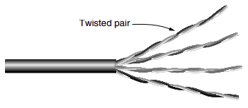
Twisted Pairs
A twisted pair consists of two insulated copper wires, typically about 1 mm thick.
Twisting is done because two parallel wires constitute a fine antenna. When the wires are twisted, the waves from different twists cancel out, so the wire radiates less effectively.
A signal is usually carried as the difference in voltage between the two wires in the pair. This provides better immunity to external noise because the noise tends to affect both wires the same, leaving the differential unchanged. One to carry signals and other as a ground reference.
The most common application of the twisted pair is the telephone system. Nearly all telephones are connected to the telephone company (telco) office by a twisted pair. Both telephone calls and ADSL Internet access run over these lines.
Twisted pairs can run several kilometers without amplification, but for longer distances the signal becomes too attenuated and repeaters are needed.
Electronics Industries Association (EIA) standards classifies twisted-pair cabling into seven categories. The garden variety deployed in many office buildings is called Category 5 cabling, or Cat 5. A category 5 twisted pair consists of two insulated wires gently twisted together. Four such pairs are typically grouped in a plastic sheath to protect the wires and keep them together.
Different LAN standards may use the twisted pairs differently. For example, 100-Mbps Ethernet uses two (out of the four) pairs, one pair for each direction. To reach higher speeds, 1-Gbps Ethernet uses all four pairs in both directions simultaneously; this requires the receiver to factor out the signal that is transmitted locally.
Through Category 6, these wiring types are referred to as UTP (Unshielded Twisted Pair) as they consist simply of wires and insulators. In contrast to these, Category 7 cables have shielding on the individual twisted pairs, as well as around the entire cable (but inside the plastic protective sheath). Shielding reduces the susceptibility to external interference and crosstalk with other nearby cables to meet demanding performance specifications..
Most common UTP connector is RegisteredJack45,
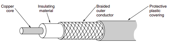
Coaxial Cable
A coaxial cable consists of a stiff copper wire as the core, surrounded by an insulating material. The insulator is encased by a cylindrical conductor, often as a closely woven braided mesh. The outer conductor is covered in a protective plastic sheath.
The outer conductor serves as a shield against the noise and as the conductor which completes the circuit.
Two kinds of coaxial cable are widely used. One kind, 50-ohm cable, is commonly used when it is intended for digital transmission from the start. The other kind, 75-ohm cable, is commonly used for analog transmission and cable television.
The construction and shielding of the coaxial cable give it a good combination of high bandwidth and excellent noise immunity. The bandwidth possible depends on the cable quality and length. Modern cables have a bandwidth of up to a few GHz.
Common type of connector used is Bayonet Neill-Concelman (BNC).
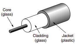
Fiber Optics
The fiber optics is made up of glass, at the center is the core through which the light propagates. The core is surrounded by a glass cladding with a lower index of refraction than the core, to keep all the light in the core using the principle of total internal reflection. Next comes a thin plastic jacket to protect the cladding. Fibers are typically grouped in bundles, protected by an outer sheath.
Two kinds of light sources are typically used to do the signaling. These are LEDs (Light Emitting Diodes) and semiconductor lasers.
Single-mode:
Highly focused source of light limits beams all close to the horizontal, All beams arrive at the destination together, Recombined with little distortion to the signal
Step-index Multi-mode:
Multiple beams move through the core in different paths. Density of the core remains constant from the center to the edges, A beam moves in a straight line until it reaches the interface of the core and the cladding. At the interface, an abrupt change due to a lower density, Suddenness of the change contributes to the distortion,
Graded-index Multi-mode:
Varying densities decreases distortion, Density is highest at the center of the core and decreases gradually to its lowest at the edge.
Defined by the ratio of the diameter of their core to the diameter of their cladding, 50/125 (Multimode, graded index, 600MHz/km), 7/125 (Single mode, 1000MHz/km), Subscriber channel (SC) connector for cable TV, Straight-tip (ST) connector for connecting cable to networking devices, Attenuation flatter than in case of twisted-pair and coaxial cable, With WDM, can transfer data at a rate of 1600 Gbps.
Advantages:
- Dramatically higher bandwidth limited not by the medium but by generation and reception,
- A signal can run 50km without regeneration, while, twisted pair drops by 90% in 1km,
- Fewer repeaters mean lower cost and fewer sources of error,
- Immunity to electromagnetic interference,
- Resistance to corrosive materials,
- Light weight,
- Does not create antenna effects,
Comparison:
| Guided Media | Frequency Range | Attenuation | Repeater Spacing |
|---|---|---|---|
| Twisted Pair [CAT 1] | 0 to 1 MHz | 0.7dB/km@1KHz | 2km |
| Coaxial Cable [DOCSIS] | 0 to 500 MHz | 7dB/km@10MHz | 1km |
| Optical Fibers | 200 to 400 THz | 0.3dB/km | 50km |
Unguided Media
Transport electromagnetic waves through free space, Ranges from 3kHz to 900THz. Concentrate signals in relatively narrow band for efficiency,
Ground propagation
Through the lowest portion of the atmosphere hugging the earth, Follow the curvature of the planet, Greater the power, greater the distance.
Sky propagation
Radiate upward into ionosphere where they are reflected back to earth. Allows for greater distances with lower output power.
Line-of-sight propagation
Transmitted in straight lines directly from antenna to antenna, Antennas directional facing each other, Tall enough or close enough not to be effected by the curvature of the earth.
Radio Waves
3KHz-1GHz, Omnidirectional, Low and medium frequencies can penetrate walls, High frequencies absorbed by rain and other obstacles, Drops 6dB per doubling in free space.
Microwave
1GHz-300GHz, Unidirectional, Cant penetrate walls, Satellites as big microwave repeaters (Communication Satellites).
| Band | Frequency range | Propagation | Applications |
|---|---|---|---|
| VLF | 3-30kHz | Ground | Radio navigation |
| LF | 30-300kHz | Ground | Locators |
| MF | 300kHz-3MHz | Sky | AM radio |
| HF | 3-30MHz | Sky | Ship and aircrafts |
| VHF | 30-300MHz | Sky and Line of sight | FM radios |
| UHF | 300MHz-3GHz | Line of sight | Cellular phones |
| SF | 3-30GHz | Line of sight | Satellites |
| EHF | 30-300GHz | Line of sight | Radars |
Infrared
300GHz-400THz Short-range communcations in a closed area using line-of-sight propagation