Network layer can be decomposed into two interacting parts, the data plane and the control plane
The data plane function of the network layer - the per router functions in the network layer that determine how a datagram arrive on one of a router’s input links is forwarded to one of that router’s output links.
The control plane functions of the network layer - the network wide logic that controls how a datagram is routed among routers along an end-to-end path from the source host to the destination host.
Traditionally the control plane routings and data-plane forwarding have been implemented together monolithicallys, within a router.
Example
Lets suppose H1 host is sending information to H2 and several routers on the path between H1 and H2. The network layer in H1 takes segments from the transport layer in H1, encapsulates each segment into a datagram, and then sends the datagrams to its nearby router, R1. At the receiving host, H2 the network layer receives the datagrams from its nearby router R2, extracts the transport layer segments, and delivers the segments up to the transport layer at H2.
The primary dataplane role of each router is to forward datagrams from its input links to its output links; primary role of the network control plane is to coordinate these local, per-router forwarding actions so that datagrams are ultimately transferred end-to-end, along paths of routers between source and destination hosts
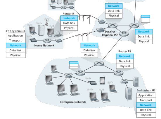
Forwarding When a packet arrives at a router’s input link, the router must move the packet to appropriate output link. A packet might also be blocked from exiting a router or might be duplicated and sent over multiple outgoing links. Forwarding refers to the router-local action of transfering a packet from an input link interface to the appropriate output link interface, takes place at very short timescales, and thus is typically implemented in hardware.
Routing The network layer must determine the route or path taken by packets as they flow from sender to receiver. A routing algorithm would determine, the path along which packets flow from H1 to H2. Routing refers to network wide process that determines the end-to-end paths that packets take from source to destination, takes place on much longer timescales and is implemented in software
How routing and forwarding are related? Note: A key element in every network router is its forwarding table, a router forwards a packet by examining the value of one or more fields in the arriving packet’s header and then use these header values to index into its forwarding table. The value stored in the forwarding table entry for those values indicates the outgoing link interface at that router to which that packet is to be forwarded. The routing algorithms determines the contents of the routers’ forwarding tables. The routing algorithm function in one router communicates with the routing algorithm function in other routers to compute the values for its forwarding table. A technically feasible case is in which network forwarding tables are configured directly by human network operators physically present at the routers, no routing protocols would be required.
Couldn’t the human approach be modified to be efficient? The approach to implementing routing functionality with each router having a routing component that communicates with the routing component of other routers -has been traditional approach adopted by routing routers. Observation that humans could configure forwarding tables suggest that there are others ways for control-plane funcitonality to determine the contents of data-plane forwarding tables. An alternate approach is where a physically seaparate from the routers, remote controller computes and distributes the forwarding tables to be used by each and every router. Remote controller might be implemented in a remote data center with high reliablity and redundnacy, and might be managed by the ISP or some third party
Network service model
Some possible services that the network layer could provide:
- Guaranteed delivery: The service guarantees that a packet sent by a source host will eventually arrive at the destination host.
- Guaranteed delivery with bounded delay: Not only guarantees delivery of the packet but delivery within a specified host to host delay bound
- In order packet delivery: Guarantees that packeets arrive at the destiation in the order that they were sent
- Guaranteed minimal bandwidth: Network layer emulates the behavior of a transmission link of a specified bit rate between sending and receiving hosts
- Security: Encrypt datagrams and decrypt them at destination
The Internet’s network layer provides a single service, known as best-effort service, with which, packets are neither guaranteed to be received in the order in which they were sent, nor is their eventual delivery guaranteed. Might appear that best-effort service is a euphemism for no service at all - a network that delivered no packets to the destination would satisfy the definition of best-effort delivery service. For example, the ATM network architecture provides for guaranteed in-order delay, bounded delay, and guaranteed minimal bandwidth.
IPv4 protocol
Two versions of IP in use today.
Key fields of IPv4 packet, referred to as a datagram:
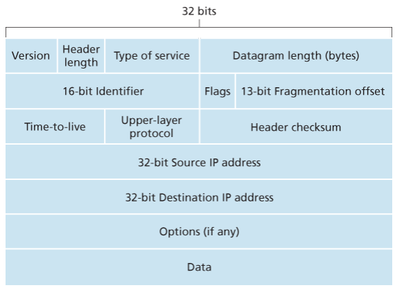
- Version number: These 4 bits specify the IP protocol version of the datagram. By looking at version can determine how to interpret remainder of the IP datagram.
- Header length: Because IPv4 datagram can contain a variable number of options, these 4 bits are needed to determine where in the IP datagram the layer i.e. the transport layer segment being encapsulated actually begins.
- Type of service: Allows different types of IP datagrams to be distinguished from each other. For example it might be useful to distinguish real-time datagrams from non-real traffic.
- Datagram length: Total length of the IP datagram (header plus data) measured in bytes. Since this field is 16 bits long, the theoretical maximum size of the IP datagram to fit in the payload field of a maximally sized Ethernet frame.
- Identifier, flags, 13-bit fragmentation offset: Have to do with so called IP fragmentation. (later)
- Time-to-live: The TTL field is to ensure that datagrams do not circulate forever, due to, for example, a long lived routing loop in the network. It is decremented by one each time the datagram is processed by a router, if the TTL reaches 0, a router must drop the datagram.
- Protocol: Typically used when an IP datagram reaches its final destination. The value of this field indicates the specific transport-layer protocol to which the data portion of this IP datagram should be passed. For example, a value of 6 indicates that the data portion is passed to TCP, while a value of 17 indicates that the data is passed to UDP.
- Header checksum: Aids a route in detecting bit errors in a received IP datagram. The header is computed by treating each 2 bytes in the header as a number and summing these numbers using 1s complement arithmetic, typically discard when there is checksum error, note that the checksum must be recomputed and stored again at each router, since the TTL filed, and possibility the options field as well, will change.
Why checksum at both TCP and IP? Only header is checksum-ed in IP while whole segment is at TCP, TCP/UDP and IP do not necessairly both have to belong to same protocol stack, TCP can run over a different network layer protocl for example ATM
- Source and destination IP addresses: When a source creates a datagram, it inserts its IP address into the source IP address filed and inserts the address of the ultimate destination into the destination IP address field.
- Options: Allow an IP header to be extended.
- Data (payload): Contains TCP or UDP packets or can carry other types of data such as ICMP messages.
The IP datagram has a total of 20 bytes of header assuming no options, if the datagram carries a TCP segment, then each non-fragmented datagram carries a total of 40 bytes of header (20 bytes of header IP + 20 bytes of TCP header) along with the application-layer messgage.
IPv4 datagram fragmentation
Not all link-layer protocols can carry network-layer packets of the same size. Some protocols can carry big datagrams, whereas other protocols can carry only little datagrams. For example, Ethernet frames can carry up to 1,500 bytes of data, whereas frames for some wide-area links can carry no more than 576 bytes.
The maximum amount of data that a link-layer frame can carry the MTU. Because each IP datagram is encapsulated within the link-layer frame for transport from one router to the next router, the MTU of the link-layer protocol places a hard limit on the length of an IP datagram.
Having a hard limit on the size of an IP datagram is not much of a problem. What is a problem is that each of the links along the route between sender and destination can use different link-layer protocols, and each of these protocols can have different MTUs.
Suppose you receive an IP datagram from one link, you check your forwarding table to determine the outgoing link, and this outgoing link has an MTU that is smaller than the length of the IP datagram. How are you going to squeeze this oversized IP datagram into the payload field of the link-layer frame? The solution is to fragment the payload in the IP datagram into two or more smaller IP datagrams, encapsulate each of these smaller IP datagrams in a separate link-layer frame; and send these frames over the outgoing link. Each of these smaller datagrams is referred to as a fragment.
Fragments need to be reassembled before they reach the transport layer at the destination. Indeed, both TCP and UDP are expecting to receive complete, unfragmented segments from the network layer.
The designers of IPv4 felt that reassembling datagrams in the routers would introduce significant complication into the protocol and put a damper on router performance. Sticking to the principle of keeping the network core simple, the designers of IPv4 decided to put the job of datagram reassembly in the end systems rather than in network routers.
IPv4 and IPv6 differences:
Under IPv4, a router that receives a network packet larger than the next hop’s MTU has two options:
- drop the packet if the Don’t Fragement (DF) flag bit is set in the packet’s header and send an ICMP message which indicates the condition Fragementation Needed
- or fragement the packet and send it over the link with a smaller MTU
Although originators may produce fragement packets, IPv6 routers do not have the option to fragment further. Instead, network equipment is required to deliver any IPv6 packets or packet fragements smaller than or equal to 1280 bytes and IPv6 hosts are required to determine the optimal MTU through Path MTU Discovery before sending packets.
For IPv4 packets, Path MTU Discovery works by setting the DF flag in the IP headers of outgoing packets. Then, any device along the path whose MTU is smaller than the packet will drop it, and send back and ICMP Fragmentation Needed message containing its MT, allowing the source host to reduce its path MTU approximately. The process is repeated until the MTU is small enough to traverse the entire path without fragmentation..
As IPv6 routers do not fragment packets, there is DF option in IPv6 header. for IPv6 Path MTU Discovery works by initially assuming the path MTU is the same as the MTU on the link layer interface where the traffic originates. Then, similar to IPv4, any device along the path whose MTU is smaller than the packet will drop the packet and send back an ICMPv6 Packet Too Big message containing its MTU, allowing the source host to reduce its path MTU appropriately.
IPv4 Addressing
Few words about how hosts and routers are connected into the Interet:
- A host typically has only a single link into the network; when IP in the host wants to send a datagram, it does over this link
- A router has multiple interfaces, oen for each of its links, IP requires each host and ruter interface to have its own IP address
- Thus an IP address is technically associated with an interface rather than with the host or router containing that interface
Each IP is 32 bits long, and thus there are total of (4 billion) possible IP addresses, typically written in so called dotted decimal in which each byte of the address is written in its decimal form and is separated by a period from other bytes in the address
Each interface on every host and router in the global internet must have an IP address that is globally unique (expect for interfaces behind NATs), but cannot be chosen in willy-nilly manner
A portion of an interface’s IP address will be determined by the subnet to which it is connected (tf is subnet?) -They give an example where three clouds are interconnected by a router in the middle -The hosts in one cloud, al lhave an IP address of the form 223.1.1.xxx, ie they have all the same leftmost 24 bits in their IP address, the interfaces are also interconnected to each other by a network that contains no routers -In IP terms, this network interconencting three host interfaces and one router interface forms a subnet -IP addressing assigns an address to this subnet: 223.1.1.0/24, where /24 slash also known as subnet mask, indicates that the leftmost 24 bits of the 32-bit quantity define the subnet address -Besides the already containing, any additional hosts attached to 223.1.1.0/24 would be required to have an address of the from 223.1.1.xxx -So there are additionally two subnets also there
(bhanesi aile subnet bhaneko router bina ko network hota?)

-The IP definition of subnet is not restricted to Ethernet segments that connect mulitple hosts to a router interface
-(again euta example aayo jasma 3 ota router triangle garayera basexan, ani harek router ko euta cloud xa, routers ko interfaces lai ni subnet bhann mildo raixa)
-Recipe for subnets:
	>To determine the subnets, detach each interface frmo its host or router, creating islands of isolated network with interfaces terminating the end points of the isolated networks, each of these isolated networks is called a subnet

(We know about the subnets in ther internet?)
-An organization with mulitple Ethernet segments and point to point links will have mluitple subnets, with all of the devices on a given subnet having the same subnet address, in principle, the different subnets could have quite different subnet addresses, in practice however, their subnet adresses often have muuch in common (what and why?)

(Okay subnets are there not that we make up, what we do is we asisgn same kind of addresses to the subnets, Why need to give like same kind of addresses in a subnet?)
-The internet's address assignment strategy is known as Classlesss Interdomain Routing (CIDR),
-CIDR generalizes the notion of subnet addressing, as with subnet addresing, the 32 bit IP address is divided into two parts and again has the dotted-decimal form a.b.c.d/x, where x indicates the number of bits in the first part of the address
-An organization is typically assigned a block of contiguous addresses, that is, a range of addresses with a common prefix
-When we cover the Internet's BGP routing protocl we will set that only thesee x leading prefix bits are considered by routers outside the organizatin's network
-WThis considerably reduces the size of the forwading table in the routers, since a single entry of the form a.b.c.d/x will be sufficeint to forwad packets to any destination outside the organization
-The remaining 32-x bits of an address can be thought of as distinguihsig among the devices within the organization, all of which have the same network prefix, these are the bits that will be considered when forwarding packets at routers within the organization
-These lower-order bits may or may not have an additional subnettting structure-

-Before CIDR was adopted, the network portions of an IP address were contrainsted to be 8, 16, or 24 bits in length, an addressing scheme known as classful addressing
-A class C /24 subnet could accomate only 254 hosts -too small for many, and class B /16 was ttoo large
-The IP broadcast address 255.255.255.255, when a hosts sends a datagram with destination address 255.255.255.255, the message is delievered to all hosts on the same subnet, routers optially forward the message into neighboring subnets as well (although they usualluy dont)

(bhanesi subnet bhanesi ta euta organization contiguous addresses dini ta hola ni)

-Need to know how hosts and subnets get their addresses in the first place

Obtaining a block of addresses:
-In order to obtain a block of IP addresses for use within an organization's subnet, a network admin might first contact its ISP, which would privde addresses from a larger block of addresses that had already been allocated to the ISP
-ISP may itself may have been allocated the address block, say 200.23.16.0/20, the turn, in turn, could divide its address block into eigh equal-sized contiguos address blocks and give one of these address blocks out to each of up to eight organizations suported by this ISP
-While obtaining a set of addresse from an ISP is one way, not the only way, there must be a way for the ISp itslef to get a block of addresses, is there a global authority that has ultimate responsiblity for managing the IP address space? and allocating addresses to ISPs and other organizations?
-Under the authority of ICANN, the ICANN allocates addresses to regional Internet registires for example, ARIN, RIPE, APNIC, and LACNIC, and handle the allocation/management wihtin their regions
Obtaining a host address: the DHCP
Once an organization has obtained a block of addresses, it can assign individual IP addresses to the host and router interfaces in its organization, a sysadmin will typically manually configure the IP addresses into the router.
Host addresses can also be configured manually, but typically done using the DHCP
A network admin can configure DHCP so that given a host receives the same IP address each time it connects to the network, or may be assigned temporary IP that will be different each time the host connects to the network
In addition, DHCP also allows a host to learn additional info, such as its subnet mask, the address of its first-hop router, and the address of its local DNS
A DHCP is a client-server protocol, a client is typically a newly arriving host wanting to obtain network configuration information -In the smples case, each subnet will have a DHCP server, if not then a DHCP relay agent, typically a router that knows the address of a DHCP server for that network is needed -(subnet nagareko bhaye ta DHCP server rakhna painithiyena hola)
For a newly arriving host, the DHCP protocol is a four step process:
- DHCP server discovery:
- The first task of a newly arriving host is to find a DHCP server with which to interact, done using a DHCP discover message, which a client sends within a UDP packet to port 67, the UDP packet is encapsulated in an IP datagrams
- The host does not even know the IP address of the network to which it is attaching, much less the address of the DHCP
- Given this the DHCP client creates a IP datagram containing DHCP discovery message along the broadcast destination IP address of 255.255.255.255 and a this host source of 0.0.0.0
- The DHCP client passes the IP datagram to the link layer, which then broadcasts this frame to all nodes attached to the subnet.
- DHCP server offers:
- A DHCP server receiving a DHCP discover message responds to the client with a DHCP offer message that is broadcast to all nodes on the subnet, again using the IP broadcast address of 255.255.255.255
- Since several DHCP servers can be present on the subnet, the client may find itself in the enviable position of being able to choose from among several offers.
- Each offer message contains the transaction ID of the received discover message, the proposed IP address for the client, the net mask, and an IP address lease time - the amount of time for which the IP address will be valid
- Common to set the lease time to several hours or days
- DHCP request:
- The newly arriving client will choose from among one or more several offers and respond to its selected offer with a DHCP request message, echoing back the configuration parameters
- DHCP ACK:
- The server responds to the DHCP request message with a DHCP ACK message, confirming the requested parameters
Since a client may want to use its address beyond the lease’s expiration, DHCP also provides a mechanism that allows a client to renew its lease on an IP address. From a mobility aspect, DHCP does have one very significant shortcoming, since a new IP address is obtained from DHCP each time a node connects to a new subnet, a TCP connection to a remote application cannot be maintained as a mobile node moves between subnets
Mobile IP - an extension to the IP infrastructure that allows a mobile node to use a single permanent address as it moves between subnets
Network Address Translation (NAT)
-Whenver a office wants to install a LAN to connect multple machines, a range of addresses would need to be allocated by the ISP to cover all of the SOHO's IP devices
-If the subnet frew bigger, a lareger block of addresses would have to be allocated, but what if the ISP had already allocated the contiguous portions of the SOHO's network's current address range?
-Answer is NAT enabled router
-The NAT enable router, residing in the home, has an interface that is part of the home network on the home side, addressing within the home network is exactly the same as we had seen, all the interfaces have the same subnet address
-The address space 10.0.0.0/8 is one of the three portions of the IP address space that is reseered for a private network
-The NAT enabled router does not look like a router to the outside world, instead the NAT router behaves to the outside world as a single device with a single IP address, in all traffic leaving the home router for the larger Internet has a source IP address of ....
-In esssence, the NAT enabled router is hiding the details of the home network from the outside world
-The router gets its single address from the ISP's DHCP server, and the router runs a DHCP server to provide addresses to computers wihtin the NAT-DHCP-router-controlle dhome network's address space

Example:
1. Suppose a user siting in home behind 10.0.0.1 requests a web page on some web server port 80 with IP 128.119.40.186, the host assigns source port number 3345 and sends the datagram into the LAN
2. The NAT router receives the datagram, generates a new source port number 5001 for the daggram, replaces the source with its WAN side IP and replces the orignal port nubmerw ith new port 5001
3. When generating new port number, the NAT router can select nay source port number that is not currently in the NAT trnaslationa table
3. The Web server blissfully unware responds with a datagram whose destination address is its IP address of the NAT router and whose desintaion port is 5001
4. When this datagram arrives at the NAT router, the router indexes the NAT trnslation table using the destinaion IP address and desintaion port number to obtain the appropriate IP address and port number
5. The router then rewrites the datagrams's destination address and desintaion port number, and forwards the datagram into the home network


NAT is a cope?
-Port numbers are meant to be used for addressing processing, not for addressing hosts, this violation can cause problems for servers running on the home network, since server processes wait for incoming requests at well-known port numbes and peers in P2P protocol need to accept incomfing connections when acting as servers
-Technical solutions to these problems include NAT traversal tools, and Universal Plug and Play uPnP, a protocl that allows a host to discover and configure a nearby NAT
-Router are meant to be layer 3 devices, and should process packets only upto the network layer, NAT violates this that hosts should be talking directly with each other, without interfering nodes modifying IP addresses, much less port numbers
-Other middleboxes also operate at the network layer but have functions that are quire different from routers, such as NAT, load balancing of traffic flows, traffic firewalling and more
IPv6
The Internet Engineering Task Force began an effort to develop a successor to the IPv4 protocol. A prime motivaiton for this effort was the realization that the 32-bit IPv4 address space was beginning to be used up, with new subnets and IP nodes being attached to the Internet (and begin allocated unique IP addresses) at a breathtaking rate.
Important changes
- Expanded addressing capabilities: IPv6 increases the size of the IP address from 32 to 128 bits. This ensures that the world won’t run out of IP addresses. Now, every grain fo sand on the planet can be IP-addressable. In addition to unicast and multicast addresses, IPv6 has introduced a new type of address, called an anycast address, that allows a datagram to be delivered to any one of a group of hosts.
- A streamlined 40-byte header: A number of IPv4 fields have been dropped or made optional. The resulting 40-byte fixed-length header allows for faster processing of the IP datagram by a router. A new encoding option allows for more flexible options processing.
- Flow labeling: IPv6 has an elusive definition of a flow. This allows labelling of packets belonging to particular flows for which the sender requests special handling, such as non-default quality of service or real-time service. For example, audio and video transmission might likely be treated as a flow.
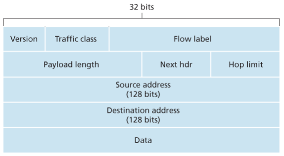
- Version. This 4-bit field identifies the IP version number.
- Traffic class: This 8-bit traffic class field, like the TOS field in IPv4, can be used to give priority to certain datagrams within a flow, or it can be used to give priority to datagrams from certain applications.
- Flow label: This 20-bit is used to identify a flow of datagrams.
- Payload length: This 16-bit value is treated as an unsigned integer giving the number of bytes in the IPv6 datagram following the fixed, 40 byte datagram header.
- Next header: This field identifies the protocol to which the contents (data filed) of this datagram will be delivered (for example, TCP of UDP).
- Hop limit: The contents of this field are decremented by one by each router that forward the datagram. If the hop limit counts reaches zero, the datagram is discarded.
- Source and destination address
- Data
No longer present in the IPv6 datagram:
- Fragmentation/reassembly: IPv6 does not allow for fragmentation and reassembly at intermediate routers; these operations can be performed only by the source and destination. If an IPv6 datagram received by a router is too large to be forwarded over the outgoing link, the router simply drops the datagram and sends a “Packet Too Big” ICMP error message back to the sender.
- Because the transport-layer (for example, TCP and UDP) and link-layer (for example, Ethernet) protocols in the Internet layers perform checksumming, the designers of IP probably felt that this functionality was sufficiently redundant in the network layer that it could be removed.
- An options field is no longer a part of the standard IP header
Transition time
Already deployed IPv4-capable systems are not capable of handing IPv5 datagrams. One option would be to declare a flag day - a given time and date when all Internet machines would be turned off and upgraded from IPv4 to IPv6. Last major transition was from using NCP to TCP almost 35 years ago.
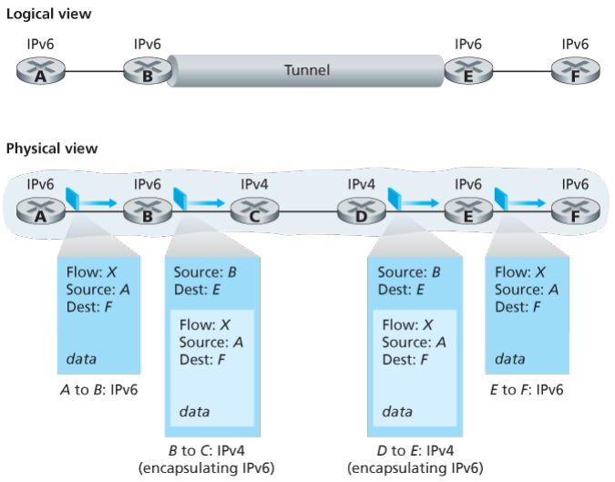
The approach to IPv4 to IPv6 that has been widely adopted in practice involves tunneling.
Suppose two IPv6 nodes want to interoperate using IPv6 datagrams but are connected to each other by intervening IPv4 routers. We refer to the intervening set of IPv4 routers between two IPv6 routers as a tunnel. With tunneling, the IPv6 node on the sending side of the tunnel takes the entire IPv6 datagram and puts it in the data (payload) field of an IPv4 datagram. This IPv4 datagram is then addressed to IPv6 node on the receiving side of the tunnel. The intervening IPv4 routers in the tunnel router this IPv4 datagram among themselves, just as though would any other datagram, blissfully unaware that the IPv4 datagram itself contains a complete IPv6 datagram. The IPv6 node on the receiving side of the tunnel eventually receives the IPv4 datagram (it is the destination of the IPv4 datagram!), determines that the IPv4 datagram contains an IPv6 datagram (by observing that the protocol number field in the IPv4 datagram is 41, indicating that the IPv4 payload is a IPv6 datagram), extracts the IPv6 datagram, and then routes the IPv6 datagram exactly as it would if it had received the IPv6 datagram from a directly connected IPv6 neighbor. …
Dual Stack:
allow IPv4 and IPv6 to coexist in the same devices and networks
… ..
..
 Generalized forwarding and SDN:
-The proliferation of middleboxes, layer-2 switches, layer3 routers, each with its own specialized hardware, software and maangement hardwrae has undoubteldy resulted in costly headaches for many network operators, however recent advances in software defined networking have promised and are now delivering, a unified appproach towards providing may of these netork layer functions, and certian link layer functions, as well in a modern, elegant, and integrated manner
.............
The Network Layer: Control Plane:
We saw that the forwarding table and the flow table were the principal elements that linked the network layer’s data and control planes. Time to learn how those forwarding and flow tables are computed, maintained and installed, two possible approaches for doing so:
-
Per-router control: Each router has a routing component that communicate with the routing components in other routers to compute the values for its forwarding table.
-
Logically centralized control: Logically centralized controller computes and distributes the forwarding tables to be used by each and every router. …
Routing algorithms
Goal is to determine good paths from senders to receivers, through network of routers. Typically good is the one that has least cost. In real world however, real world concerns such as policy issues such as “router x belonging to Y should not forward any packets originating from network owned by Z” also come into play.
A graph is used to formulate routing problems, the nodes in the graph represent routers -the points at which packet-forwarding decisions are made >Edges repsent the links between these routers, typically a edge’s cost may reflect physical length of the corresponding link (for ex, a transoceanic link might have a higehr cost than a short-haul terrestial), the link speed, or the monetary cost associated with a link
-Assume that edge costs are determined and not care how calculaed

-For any edge (x,y) in E, denote c(x,y) as the cost of the edge between nodes x and y, if the pair (x,y) does not belong to E, set c(x,y) = inf
-All are undirected graphs.
-Given that costs are assigned to various edges in the graph abstraction, a natural goal of a routing algorithm is to identify the least costly paths betwwen sources and destinations
-In precise:
	>A path in a graph G=(N,E) is a sequence of nodes (x1,x2,...,xp) such that teach of the pairs (x1,x2)... are edges in E
	>The cost of a path is simply the sum of al the edge costs along the path ie C(x1,x2)+...
-
A centralized routing algorithm: Computes the least-cost path between a source and destination using complete, global knowledge about the network. That is, the algorithm takes the connectivity between all nodes and all link costs as inputs. This requires that algorithm somehow obtain this information before actually performing the calculation. The calculation itself can be run at one site, a logically centralized controller or could be replicated in the routing component of each and every router. Key distinguishing feature is that the algorithm has complete information about connectivity and link costs. Algorithms with global state information are often refereed as link-state algorithms, since must be aware of the cost of each link in the network.
-
A decentralized routing algorithm: The calculation of the least-cost path is carried in an iterative, distributed manner by the routers. No node has complete information about the costs of all network links. Instead, each node begins with only the knowledge of the costs of its own directly attached links. Then, through an iterative process of calculation and exchange of information with its neighboring nodes, a node gradually calculates the least-cost path to a destination or set of destinations. The decentralized algorithm is called a distance-vector algorithm because each node maintains a vector of estimates of the costs (distances) to all other nodes in the network. Such decentralized, with interactive message exchange between neighboring routers is more naturally suited to control planes where the routers interact directly with each other.
A second broad way to classify routing algorithms is according to whether they are static or dynamic, in static routing, routes change very slowly over item, often as a result of human intervention , a human manually editing link costs. Dynamic routing algorithms change the routing paths as the network traffic loads or topology change. A dynamic algorithm can be run either periodically or in direct response to topology or link cost changes. While dynamic algorithms are more responsive to network changes, they are also more susceptible to problems such as routing loops and route oscillation.
A third way to classify is according to whether they are load-sensitive or load-insensitive. In load-sensitive, link costs vary dynamically to reflect the current level of congestion in the underlying link. If a high cost is associated with a link that is currently congested, a routing algorithm will tend to choose routers around such a congested link.
The Link-State Routing:
In a link-state algorithm, the network topology and all link costs are known, i.e. available as input to the LS algorithm. In practice, this is accomplished by having each node broadcast link-state packets to all other nodes in the network, with each link-state packet containing the identities and costs of its attached links. In practice, for example, the Internets OSPF routing protocol is accomplished by a link-state broadcast algorithm. The result of the nodes’ broadcast is that all nodes have an identical and complete view of network. Each node can then run the LS algorithm and compute the same set of least-cost paths as every other node.
Dijkstra’s is one and closely related is Prim’s. Dijkstra algorithm calculates the least cost path from one node (the source, say ) to all other nodes in the network. It is always iterative and has the property that after the th iteration of the algorithm, the least cost path are known to destination nodes, and among the least-cost to all destination nodes, these paths will have the smallest cost.
With the notations
- : cost of the least-cost path from the source node to destination as of this iteration of the algorithm.
- : subsets of least path known nodes; is in if the least cost path from source to is definitely known.
Initialization:
	N' = {u}
	for all nodes v:
		if v is a neighbor of u
			D(v) = c(u,v)
		else
			D(v) = inf

Loop:
	find w not in N' such that D(w) is a minimum
	add w to N'
	update D(v) for each neighbor v of w and not in N'
		D(v) = min(D(v), D(w)+C(w,v))
until N' = N
When the LS algorithm terminates, we have, for each node, its predecessor along the least-cost path from the source code. The forwarding table in a node can be constructed from this information by storing, for each destination, the next-hop node on the least-cost path from to the destination .
Complexity
Given nodes, not counting the source, how much computation must be done in the worst case to find the least-cost paths from the source to all destinations? In the first iteration, we need to search through all n nodes to determine the node, , not in that has the minimum cost. In the second iteration, we need to check nodes to determine the minimum cost; in the third iteration nodes, and so on. Overall, the total number of nodes we need to search through over all the iterations is , thus the LS algorithm has worst-case complexity of order . A more sophisticated implementation using heap can find the minimum in logarithmic rather than linear time.
—Some pathology when using congestion based metrics—
The Distance-Vector Routing Algorithm
Whereas the LS algorithm is an algorithm using global information, DV is iterative, asynchronous and distributed
- in that each node receives some information from one or more of its directly attached neighbors, performs a calculation, and then distributes the results of its calculation back to its neighbors;
- continues on until no more information is exchanged between neighbors;
- does not require all of the nodes to operate in lockstep with each other.
The basic idea is that each node begins with an estimate of the distance vector, which is the cost estimates from a node to all other nodes in N. With the DV algorithm, each node maintains the distance vector of each of its neighbors.
From time to time, each node sends a copy of its distance vector to each of its neighbors, when a node receives a new distance vector from any of its neighbors , it saves ‘s distance vector, and then uses the Bellman Ford to update its own distance vector as follows If node distance vector has changed as a result of this update step, node will then send its updated distance vector to each of its neighbors, which can in turn update their own distance vectors.
As long as all the nodes continue to exchange their distance vectors in an asynchronous fashion, each estimate converges to the actual cost of the least-path from node to node .
At each node :
Initialization:
	for all nodes v:
		if v is a neighbor of x
			D_x(v) = c(x,v)
		else
			D_x(v) = inf
	for each neighbor v
		send distance vector to w

Loop:
	wait (until I see a link cost change to some neighbor or
			until I receive a distance vector from some neighbor)
	for each v in N:
		D_x(v) = min_w(c(x,w), D_w(v)) where w are neighbors
	if D_x(v) changed for any destination y
		send distance vectors to all neighbors
The DV is decentralized and only information a node will have is the costs of the links to its directly attached neighbors and information it receives from these neighbors.
Count to infinity
…
Comparison of LS and DV Routing:
In the DV algorithm, each node talks to only its directly connected neighbors and provides with least-cost estimates from itself to all the nodes in the network while the LS algorithm requires global information i.e. the network topology and all link costs are available are inputs.
- Message complexity
- LS require each node to know the cost of each link in the network, requires messages to be sent. Whenever a link cost changes, the new cost must be sent to all nodes.
- The DV requires message exchanges between directory connected neighbors at each iteration. When link cost changes, the DV will propagate the results of the changed link cost only if the new link cost results in a changed least-cost path for one of the nodes attached ot that link.
- Speed of convergences
- The implementation of LS is requiring .
- DV can converge slowly and can have routing loops while the algorithm is converging. DV suffers from count-to-infinity problem.
- Robustness:
- When a router fails, under LS, a router could broadcast an incorrect cost for one of its attached links but no others. A node could corrupt or drop packets it received as part of an LS broadcast. But an LS node is computing its own forwarding tables; other nodes are performing similar calculations for themselves. This means route calculations are somewhat separated under LS.
- Under DV, a node can advertise incorrect least-cost paths to any or all destinations. In this sense, an incorrect node calculation can be diffused through the entire network under DV.
OSPF: Intra-AS Routing
So far, one router was indistinguishable from another in the sense that all routers executed the same routing algorithm to compute routing paths through the entire network. In practice, this model of homogeneous set of routers all executing the same routing algorithm is simplistic.
- Storing routing information for possible destination at each of the routers in Internet would require enormous amounts of memory. The overhead required to broadcast connectivity and link cost updates among all of the routers would be huge.
- An ISP desires to operate its network as it pleases or to hide aspects of internal organization from the outside.
Both of these can be solved by organizing routers into autonomous systems (ASs), with each AS consisting of a group of routers that are under the same administrative control. Often the routers in an ISP constitute a single AP, some ISPs partition their network into multiple ASs. An AS is identified by its globally unique autonomous system number, assigned by ICANN reigistries.
Routers within the same AS will run the same routing algorithm and have information about each other. The routing algorithm running within an autonomous system is called an intra-autonomous system routing protocol.
OSPF and its closely related cousin IS-IS, are widely used intra-AS routing in the Internet. OSPF is a link-state protocol that uses flooding of link-state information and a Dijkstra’s least-cost path algorithm. With OSPF, each router constructs a complete topological map of the entire autonomous system. Each router then locally runs Dijkstra’s shortest-path algorithm to determine a shortest-path tree to all subnets, with itself as the root.
Individual link costs are configured by the network admin. The admin might choose to set all link costs to 1, thus achieving minimum-hop routing, or might choose to set the link weights to be inversely proportional to link capacity in order to discourage traffic from using low-bandith links.
WIth OSPF, a router broadcasts routing info to all other routers in the AS, not just to the neighboring routers. A router broadcasts link-state information whenever there is a change in a link’s state. It also broadcasts periodically at least once every 30 minutes, even if the link’s state has not changed.
OSPF advertisements are contained in OSPF messages that are carried directly by IP, with an upper-layer protocol of 89 for OSPF. Thus, the OSPF protocol must itself implement functionality such as reliable message transfer and link-state broadcast. The OSPF protocol also checks that links are operational (via a HELLO message that is sent to an attached neighbor) and allows an OSPF router to obtain a neighboring router’s database of network-wide link state.
…(inter area whatever shit)…
Routing among the ASs: BGP:
When routing a packet between a source and destination within the same AS, the route the packet follows is entirely determined by the intra-AS routing protocol.
However, to route a packet across multiple ASs, say from a smartphone in Timbuktu to a server in a datacenter in Silicon Valley, we need an inter-autonomous system routing protocol.
Since an inter-AS routing protocol involves coordination among multiple ASs, communicating ASs must run the same inter-AS routing protocol. In fact, in the Internet, all ASs run the same inter-AS routing protocol, called the Border Gateway Protocol, more commonly known as BGP.
BGP is a decentralized and asynchronous protocol in the vein of distance-vector.
In BGP, packets are not routed to a specific destination address, but instead to a CIDRized prefixes, with each prefix representing a subnet or a collection of subnets. In the world of BGP, a destination may take the form 138.16.68/22, which includes 1,024 IP addresses. Thus a router running BGP forwarding table will have the entries of the form , where is a prefix and is an interface number for one of the router’s interfaces.
As an inter-AS routing protocol, BGP provides each router a means to:
- Obtain prefix reach-ability information from neighboring ASs. In particular, BGP allows each subnet to advertise its existence to the rest of the Internet.
- Determine the best routes to the prefixes. A router may learn about two or more different routes to a specific prefix. To determine the best route, the router will locally run a BGP route selection procedure using the prefix reachability information it obtained via neighboring routers. The best route will be determined based on policy as well as the reach-ability information.
Can you on surface tell me in terms of AS and not what individual routers do?
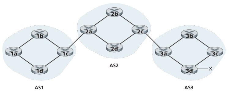 Consider the task of advertising reliability information for prefix to all of the routers. First AS3 sends a BGP message to AS2, saying that exists and is in AS3. Then AS2 sends a BGP message to AS1, saying that exists and that you can get to by first passing through AS2 and then going to AS3.
Now in terms of routers For each AS, each router is either a gateway router or an internal router. A gateway router is a router on the edge of an AS that directly connects to one or more routers in other ASs. An internal router connects only to hosts and routers within its own AS. In BGP, pairs of routers exchange routing information over semi-permanent TCP connections using port 179.
Wait BGP uses TCP? I guess it does man OSPF chai directly to some protocol in IP packet ma haldinxa, BGP le chai use garxa jasto xa.
Each such TCP connection, along with all the BGP messages sent over the connection, is called a BGP connection. Furthermore, a BGP connection that spans two ASs is called an external BGP (eBGP) connection, and a BGP session between routers in the same AS is called an internal BGP (iBGP) connection.
In order to propagate the reachability information, both iBGP and eBGP sessions are used. In this process, gateway router 3a first sends an eBGP message “AS3 x” to gateway router 2c. Gateway router 2c then sends the iBGP message “AS3 x” to all of the routers in AS2, including to gateway router 2a. Gateway router 2a then sends the eBGP message “AS2 AS3 x” to gateway router 1c. Finally, gateway router 1c uses iBGP to send the message “AS2 AS3 x” to all the routers in AS1. After this process is complete, each router in AS1 and AS2 is aware of the existence of x and is also aware of an AS path that leads to x.
What if there are multiple paths?
Consider the network with an additional physical link from router 1d to router 3d, in this case, there are two paths from AS1 to x: the path “AS2 AS3 x” via router 1c; and the new path “AS3 x” via router 1d. In fact, in the Internet, routers often receive rechability information about dozens of different possible paths.
When a router advertises a prefix across a BGP connection, it includes with the prefix several BGP attributes. In BGP jargon, a prefix along with its attributes is called a route. Two of the more important attributes are AS-PATH and NEXT-HOP. The AS-PATH attribute contains the list of ASs through which the advertisement has passed. To generate the AS-PATH value, when a prefix is passed to an AS, the AS adds its ASN to the existing list in the AS-PATH.
BGP routers also use the AS-PATH attribute to detect and prevent looping advertisements; specially, if a router sees that its own AS is contained in the path list, it will reject the advertisement. For example, there are two routes from AS1 to subnet x: one which uses AS-PATH “AS2 AS3” and another that uses the AS-PATH “A3”.
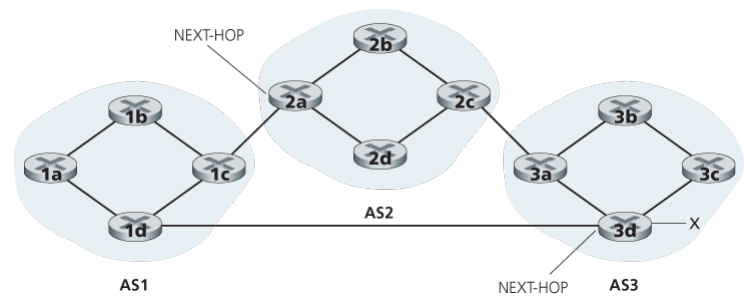
Providing the critical link between the inter-AS and intra-AS routing protocols, the NEXT-HOP attribute has a subtle but important use. The NEXT-HOP is the IP address of the router interface that begins the AS-PATH. In the same example, the NEXT-HOP attribute for the route “AS2 AS3 x” from AS1 to x that passes through AS2 is the IP address of the left interface on router 2a. The NEXT-HOP attribute for the route “AS3 x” from AS1 to x that bypasses AS2 is the IP address of the leftmost interface of router 3d.
Here, each BGP route is written as a list with three components: NEXT-HOP; AS-PATH; destination prefix. Note that the NEXT-HOP attribute is an IP address of a router that does not belong to AS1; however, the subnet that contains this IP address directly attaches to AS1.
How does 1b reach x?
The 1b router will learn about two possible BGP routes to prefix x. In hot potato routing, the route chosen is that route with the least cost to the NEXT-HOP router beginning that route. In this example, router 1b will consult its intra-AS routing information to find the least-cost intra-AS path to NEXT-HOP router 2a and the least-cost intra-AS path to NEXT-HOP router 3d, and then select the route with the smallest of these least-cost paths.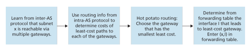 …
…
When a router selects a route to a destination, the AS routing policy can trump all other considerations, such as shortest AS path or hot potato routing. Indeed, in the route-selection algorithm, routes are first selected according to the local-preference attribute, whose value is fixed by the policy of the local AS.
(some general way is also given here brother)
ICMP
The Internet Control Message Protocol (ICMP) is used by hosts and routers to communicate network-layer information to each other. The most typical use of ICMP is for error reporting. For example, when running an HTTP session, you may have encountered an error message such as “Destination network unreachable”. This message had its origin in ICMP. At some point, an IP router was unable to find a path to the host specified in your HTTP request. That router created and sent an ICMP message to your host indicating the error.
ICMP is often considered part of IP, but architecturally it lies just above IP, as ICMP messages are carried inside IP datagrams. That is, ICMP messages are carried as IP payload, just as TCP or UDP segments are carried as IP payload. Similarly, when a host receives an IP datagram with ICMP specified as the upper-layer protocol (an upper-layer protocol number of 1), it demultiplexes the datagram’s contents to ICMP, just as it would demultiplex a datagram’s content to TCP or UDP.
ICMP messages have a type and a code field, and contain the header and the first 8 bytes of the IP datagram that caused the ICMP message to be generated in the first place (so that the sender can determine the datagram that caused the error).
The well-known ping program sends an ICMP type 8 code 0 to the specified host. The destination host, seeing the echo request, sends back a type 0 code 0 ICMP echo reply. Most TCP/IP implementations support the ping server directly in the operating systems; that is, the server is not a process.
Destination Host Unreachable Source Quench Time Exceeded Echo Request and Reply
SNMP
(simple network management protocol, something about software defined networking iguess)
Our Internet IP is very not hard working
The connection oriented technologies are MPLS (MultiProtocol Label Switching) and VLANs.
For connection-oriented service, we need a virtual-circuit network. The idea behind virtual circuits is to avoid having to choose a new route for every packet sent. Instead, when a connection is established, a route from the source machine to the destination machine is chosen as part of the connection setup and stored in tables inside the routers. That route is used for all traffic flowing over the connection, exactly the same way that the telephone system works. When the connection is released, the virtual circuit is also terminated. With connection-oriented service, each packet carries an identifier telling which virtual circuit it belongs to.
(description of how this process works)
In some context, this process is called label switching. An example of a connection-oriented network service is MPLS (MultiProtocol Label Switching). It is used within ISP networks in the Internet, with IP packets wrapped in an MPLS header having a 20-bit connection identifier or label. MPLS is often hidden from customers, with the ISP establishing long-term connections for large amounts of traffic, but it is increasingly being used to help when quality of service is important but also with other ISP traffic management tasks
MPLS adds a label in front of each packet, and forwarding is based on the label rather than on the destination address. Making the label an index into an internal table makes finding the correct output line just a matter of table lookup. Using this technique, forwarding can be done very quickly.
This advantage was the original motivation behind MPLS, which began as proprietary technology known by various names including tag switching.
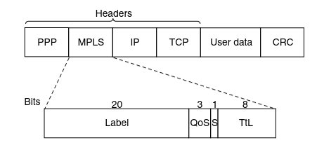
The first question to ask is where does the label go? Since IP packets were not designed for virtual circuits, there is not field available for virtual-circuit numbers within the IP header. For this reason, a new MPLS header had to be added in front of the IP header.
The generic MPLS header is 4 bytes long and has four fields. Most important is the Label field, which holds the index. The QoS field indicates the class of ser- vice. The S field relates to stacking multiple labels (which is discussed below). The TtL field indicates how many more times the packet may be forwarded. It is decremented at each router, and if it hits 0, the packet is discarded. This feature prevents infinite looping in the case of routing instability
Since most hosts and routers do not understand MPLS, we should also ask when and how the labels are attached to packets. This happens when an IP packet reaches the edge of an MPLS network. The Label Edge Router inspects the destination IP address and other fields to see which MPLS path the packet should follos, and puts the right label on the front o fthe packet. Wihin the MPLS network, tthis label is sued to forward the packet. At the other eddge, of the MPLS network, the label has served its prupose and is removed, releaving the IP packet again for the next network.