X.25
Packet-switching protocol for wide area network (WANs) connectivity that uses a public data network (PDN). X.25 was developed by common carriers in early 1970s and approved by CCITT, the precursor of the International Telecommunication Union (ITU), and was designed as a global standard for a packet-switching network.
The standard operated only at 19.2 Kbps, but this was generally sufficient for character-based communication between mainframes and terminals.
Newer WANs technologies such as frame relay, T-carrier services are now generally preferred over X.25. However, X.25 networks still have applications in areas such as credit card verification, and other dedicated business and financial uses.
The X.25 standard corresponds in functionality to the first three layers of OSI reference model for networking.
- The physical layer interface for connecting data terminal equipment (DTE), such as computers and terminals at the customer premises, with the data communications equipment (DCE), such as X.25 packet switches at the X.25 carrier’s facilities. The physical layer interface of X.25 is called was derived from the RS-232 interface for serial transmission.
- The data-link layer protocol called Link Access Procedure, Balanced (LAPB), which defines encapsulation (framing) and error-correction methods. LAPB also enables the DTE or the DCE to initiate or terminate a communication session or initiate data transfer.
- The network layer protocol called the Packet Layer Protocol (PLP), which defines how to address and deliver X.25 packets between end nodes and switches on an X.25 network using permanent virtual circuits (PVCs) or switched virtual circuits (SVCs). This layer is responsible for call setup and termination and for managing transfer of packets
The X.25 network consists of a backbone of X.25 that are called packet switching exchanges (PSEs). These switches provide packet-switching services that connect DCEs at the local facilities of X.25 carriers. You can connect several DTEs to a single DCE by using the multiplexing methods inherent in the X.25 protocol.
An end node (DTE) can initiate a communication session with another end node by dialing its X.121 address and establishing a virtual circuit that can be either permanent or switched, depending on the level of service required.
Packets are routed through the X.25 backbone network by using the ID number of the virtual circuit established for the particular communication session. This ID number is called the logical channel identifier (LCI) and is a 12-bit address that identifies the virtual circuit.
Packets are generally up to 128 bytes in size, although maximum packet sizes range from 64 to 4096 bytes, depending on the system.
Disadvantages
- Efficient for file transfer but not for interactive communication such as Telnet sessions, in which TCP/IP is run over X.25.
- Another reason that X.25 is inefficient for interactive communication is the typical half-second latency in due to the store-and-forward nature of the packet-switching network. Frame relay does not use store-and-forward packet switching and hence has much less latency.

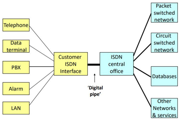
ISDN
Integrated Services Digital Network (ISDN) is a set of communication standards for simultaneous digital transmission of voice, data, and other network services over the digitalised circuits of the public switched telephone networks (PSTN). ISDN has been largely been replaced with digital subscriber line (DSL) systems of much higher performance.
Integrated services refers to ISDN’s ability to deliver at minimum two simultaneous connections, in any combination of data, voice, video, and fax, over a single line.
In ISDN, there are two types of channels, B for bearer and D for data. B channels are used for data which may include voice, and D channels are intended for signaling and control but can also be used for data.
There are two ISDN implementations.
- Basic Rate Interface (BRI), also called basic rate access (BRA) - consists of two B channels, each with bandwidth of 64 kbit/s, and one D channel with a bandwidth of 16 kbit/s. Together these three channels can be designated as 2B+D.
- Primary Rate Interface (PRI), also called primary rate access (PRA) in Europe - contains a greater number of B channels and a D channel with bandwidth of 64 kbit/s. The number of B channels for PRI varies according to the nation: in North America and Japan it is 23B+1D, with an aggregate bit rate of 1.544 Mbit/s (T1); in Europe, India and Australia it is 30B+D, with an aggregate bit rate of 2.048 Mbit/s (E1).
The D channel can also be used for sending and receiving X.25 data packets, and connection to X.25 packet network.
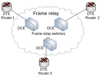
Frame Relay
Frame Relay is a standardized wide area network (WAN) technology that specifies the physical and data link layers of digital telecommunications channels using a packet switching technology.
Originally designed for transport across ISDN infrastructure. Its designers aimed to enable a packet-switched network Packet-switched network” to transport over circuit-switched technology. The technology has become a stand-alone and cost-effective means of creating a WAN.
Frame Relay has its technical base in the older X.25 technology, designed for transmitting data on analog voice lines. Unlike X.25, whose designers expected analog signals with a relatively high chance of transmission errors, Frame Relay is a fast switching technology operating over links with a low chance of transmission errors, which means that the protocol does not attempt to correct errors.
It’s designers aimed to enable a packet-switched network to transport over circuit-switched technology. The technology has become a stand-alone cost-effective means of creating a WAN.
Needs less powerful switching centers and with less memory capacity than those needed by X25 as each X25 switching center uses receive-store-check-relay method, while frame relay does not need checking or correcting errors.