Classic vs Switched.
Classic
A single long cable to which all computers were attached,
| Preamble, SoF | Dst address | Src address | Length/Type | Data | Pad | Checksum |
|---|---|---|---|---|---|---|
| 8 | 6 | 6 | 2 | 0-1500 | 0-46 | 4 |
Manchester preamble to synchronize clocks, Pad fills the frame to the minimum size, Checksum is 32-bit CRC, Dst addresses with first bit 1 are for multi-casting group, On detecting collision, generates 48-bit noise burst to warn other stations, Slot time set to 512 bit times, or 51.2sec, After collisions, a random number of slots between and skipped, Number of contention slots is never more than , With a data rate of 10 Mbps, efficiency is 85.
Ethernet frame structue:
	1. Data field (46 to 1500 bytes): Carries IP datagram, if IP exceeds 1500 bytes then host has to fragement the datagram, the minimum size of the data is 46 bytes, so data filed has to be stuffed when stuffing is used, the data passed to the network layer contains the stuffin as well as an IP datagram

	2. Destination address (6 bytes): Contains MAC address of the destination adapter, BB-BB..., when B receives an Ethernet frame whose destinaiton address is either BB.. or MAC broadcast address, it passes the contents of the frame's data field to the network layer; if it receives a frame with any other MAC address, discards the frame

	3. Source address (6 bytes): COntains MAC of the adapter that transmits the frame onto the LAN

	4. Type field (2 bytes): The type field permits Ethernet to multiplex network layer protocols , IP and other network procols, for ex: Novell IPX or AppleTalk each have their own standardied type number, furthermore, ARP protocol has its own type number, and if the arriving frame conatains an ARP packet, will be demultiplexed up to the ARP protoocl

	5 Cyclice redundancy cehck (CRC) (4 bytes):

	6. Preamle (8 bytes): Ethernet frame begins with an 8-byte preamble filed, each of the first 7 bytes of the preamble has a value of 10101010; the byte is 10101011, the first 7's server to wake up the receiving adapters and to synchronize their clocks to that of the sender's clock, need synchrnzation because an adapter will drift from its actual target rate, the last 2 bits of the eight byte of the premable alert the adapter that the important stuff is about to come
In addition to there being a maximum frame length, there is also a minimum frame length. While a data field of 0 bytes is sometimes useful, it causes a problem. When a transceiver detects a collision, it truncates the current frame, which means that stray bits and pieces of frames appear on the cable all the time. To make it easier to distinguish valid frames from garbage, Ethernet requires that valid frames must be at least 64 bytes long, from destination address to checksum, including both. If the data portion of a frame is less than 46 bytes, the Pad field is used to fill out the frame to the minimum size.
Classic Ethernet uses the 1-persistent CSMA/CD algorithm. This descriptor just means that stations sense the medium when they have a frame to send and send the frame as soon as the medium becomes idle. They monitor the channel for collisions as they send. If there is a collision, they abort the transmission with a short jam signal and retransmit after a random interval. After the first collision, each station waits either 0 or 1 slot times at random before trying again. If two stations collide and each one picks the same random number, they will collide again. After the second collision, each one picks either 0, 1, 2, or 3 at random and waits that number of slot times. If a third collision occurs (the probability of this happening is 0.25), the next time the number of slots to wait is chosen at random from the interval 0 to 2^3 − 1.
Hub, Bridge and Switch Ethernet
Easy to add or remove new stations,
Connect LANs maintaining capacity,
 Switches port frames directly to destination,
Independent collision domains,
Multiple frames sent simultaneously,
Buffering mechanism,
Transparent,
Maintain a hash table listing each possible destination and output port it belongs on,
Backward learning algorithm,
Updated with current time,
Three cases,
Redundancy,
Spanning tree,
Implemented with special-purpose VLSI chips,
Switches port frames directly to destination,
Independent collision domains,
Multiple frames sent simultaneously,
Buffering mechanism,
Transparent,
Maintain a hash table listing each possible destination and output port it belongs on,
Backward learning algorithm,
Updated with current time,
Three cases,
Redundancy,
Spanning tree,
Implemented with special-purpose VLSI chips,
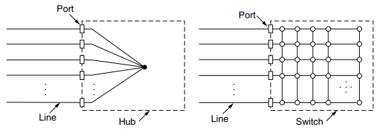
(Description:) Ethernet soon began to evolve away from the single long cable architecture of classic Ethernet. The problems associated with finding breaks or loose connections drove it toward a different kind of wiring pattern, in which each station has a dedicated cable running to a central hub. A hub simply connects all the attached wires electrically, as if they were soldered together. However, hubs do not increase capacity because they are logically equivalent to the single long cable of classic Ethernet.
Fortunately, there is an another way to deal with increased load: switched Ethernet. The heart of this system is a switch containing a high-speed backplane that connects all of the ports. A switch has the same advantages as a hub, too. It is easy to add or remove a new station by plugging or unplugging a wire, and it is easy to find most faults since a flaky cable or port will usually affect just one station. There is still a shared component that can fail—the switch itself—but if all stations lose connectivity the IT folks know what to do to fix the problem: replace the whole switch.
Inside the switch, however, something very different is happening. Switches only output frames to the ports for which those frames are destined. When a switch port receives an Ethernet frame from a station, the switch checks the Ethernet addresses to see which port the frame is destined for. In a hub, all stations are in the same collision domain. They must use the CSMA/CD algorithm to schedule their transmissions. In a switch, each port is its own independent collision domain. In the common case that the cable is full duplex, both the station and the port can send a frame on the cable at the same time, without worrying about other ports and stations.
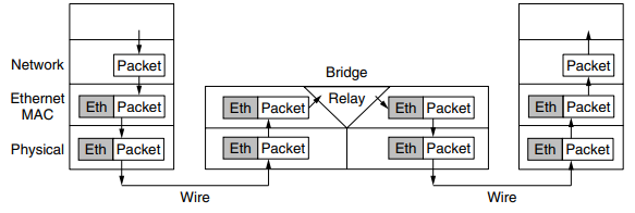
(SEGWAY TO BRIDGES) Many organizations have multiple LANs and wish to connect them. Would it not be convenient if we could just join the LANs together to make a larger LAN? In fact, we can do this when the connections are made with devices called bridges. The Ethernet switches are a modern name for bridges; they provide functionality that goes beyond classic Ethernet and Ethernet hubs to make it easy to join multiple LANs into a larger and faster network.
Two separate LANs have twice the capacity of a single LAN. Bridges let the LANs be joined together while keeping this capacity. The key is not to send traffic onto ports where it is not needed, so that each LAN can run at full speed.
This step of switches and bridges requires the switch to be able to work out which ports correspond to which addresses. A simple way to implement this scheme is to have a big (hash) table inside the bridge. The table can list each possible destination and which output port it belongs on. When the bridges are first plugged in, all the hash tables are empty. None of the bridges know where any of the destinations are, so they use a flooding algorithm: every incoming frame for an unknown destination is output on all the ports to which the bridge is connected except the one it arrived on. As time goes on, the bridges learn where destinations are. Once a destination is known, frames destined for it are put only on the proper port; they are not flooded.
-All of the Ethernet technologies provide connectionless service to the network layer, ie when adapter A wants to send a datagram to adapter B, adapter A encapuslates the datagram in an Ethernet frame and sends the frame into the LAN, without first handshaking with B
-Provide an unreliable serice to the network layer, specifically, when B revices a frame from A, it runs the fram ethrough CRC check, but niether sends an acknowledgement nor a negative acnolwedgement when a frame fails, simply discards the frame
-Helps to make Ethernet cheap

Ethernet Technologies:
	-Ethernet comes in many different flaovours such as 10BASE-T, 10BASE-2, 100BASE-T, 1000BASE-LX, 10GBASE-T and 40GBASE-T standardized over year by IEEE 802.3 CSMA/CD
	-BASE refers to baseband Ethernt meaning that the physical media only carries Ethernet traffic; almost all of the 802.3 standards are for baseband Ethernet
	-10, 100, 1000 or 10 G etc are for 10 Megabits per seconds and so on
	-Final part refers to the physical media itself; Ethernet is both a link-layer and a physical-layer speciification and is carried over a variety of physical media including coaxial cable, copper wire and fiber, a 'T' refers to twisted copper wires

	-40 Gigabit maintains full compativility with the huge installed base of Ehternet equipment, does the following:

	1. Uses the standard Ethernet frame format and is backward compatible with 10BASE-T and 100BASE-T technologies, allows for easy intergation of GIgabit Ethernet with the existing installed base of Ethernet equipment
	2. Allows for pont to point links as well as shared broadcast channels, PPP uses siwtches while broadcast channels use hubs, in Ethernet jargons, hubs are called buffered distributors
	3. Uses CSMA/CD for shared broadcast channels, in order to have acceptable effiicency, the maixmum distance between nodes must be severely restribted
	4. Allows for full-duplex operation at 40 Gbps in both directions

	=The prevalent use of Ethernet today is switch based star topology, using store-and-forward packet switching, is there really a need anymore for an Ethernet MAC protocol?
	-A switch coordaintes its transmssion and never forwards more than one frame onto the same interface at any time, furthermore, modern switches are full-dupled so that a switch and a node can each send frames to each other at the same time wihtout interference, in other words, in a switch based Ethernet LAN there are no collisions and therefor there is no need for a MAC protocol
Virtual LAN
Modern institutional LANs are often configured hierarchically with each department having its own switched LAN connected to the switched LANs of other groups via a switch hierarchy. For example, if a company wants k LANs, it could buy k switches. By carefully choosing which connectors to plug into which switches, the occupants of a LAN can be chosen in a way that makes organizational sense, without too much regard to geography.
Does it matter who is on which LAN? After all, in nearly all organizations, all the LANs are interconnected. In short, yes, it often matters. Network administrators like to group users on LANs to reflect the organizational structure rather than the physical layout of the building, for a variety of reasons.
In response to customer requests for more flexibility, network vendors began working on a way to rewire buildings entirely in software. The resulting concept is called a VLAN (Virtual LAN). It has been standardized by the IEEE 802 committee and is now widely deployed in many organizations.
Drawbacks of non-VLAN configurations:
- Lack of traffic isolation:
- Although hierarchy localizes group traffic to within a single switch, broadcast traffic (e.g. frames carrying ARP and DHCP messages or frames whose destination has not yet been learned by a self-learnign switch) must still traverse the entire institutional newtork
- Limiting broadcast traffic scope would improve LAN performance, also for security/privacy concerns.
-
Inefficient use of switches:
-
Managing users:
- If an employee moves between gorups, the physical cabling must be changed to connect the employee to a different switch
(aba switch hierarchy will represent building structure, while, vlan will do logical)
VLANs are based on VLAN-aware switches. To set up a VLAN-based network, the network administrator decides how many VLANs there will be, which computers will be on which VLAN, and what the VLANs will be called.
To make the VLANs function correctly, configuration tables have to be set up in the bridges. These tables tell which VLANs are accessible via which ports. To implement this scheme, bridges need to know to which VLAN an incoming frame belongs. If we were designing a new type of LAN, it would be easy enough to just add a VLAN field in the header. But what to do about Ethernet, which is the dominant LAN, and did not have any spare fields lying around for the VLAN identifier? The IEEE 802 committee had this problem thrown into its lap in 1995. After much discussion, it did the unthinkable and changed the Ethernet header. The new format was published in IEEE standard 802.1Q, issued in 1998.